Supermicro C2558 Lan Bypass Motherboard.

Notice: Page may contain affiliate links for which we may earn a small commission through services like Amazon Affiliates or Skimlinks.

Tegan

New Member
Jan 31, 2011
13
6
3
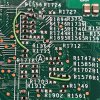
Here is the board:
IMG_3466low.jpg
Here is the only marking on the back:
IMG_3465.jpg
Here is the area with the additional wiring:
IMG_3464.jpg
And one more close-up:
IMG_3457.jpg

When it boots, it shows:

"Version 2.16.1243. Copyright (C) 2013 American Megatrends, Inc.
Citrix SD-WAN 410 BIOS Date: 10/27/2016 18:10:10 Ver: 6.0c"

The BIOS says that its build date is 10/24/2016, project version 6.0c.

Also, it takes about 45 seconds before you can get into the BIOS or see anything via console.

Hopefully that covers what you were looking for.
 

ericloewe

Active Member
Apr 24, 2017
295
129
43
30
When the issues originally surfaced, I recall seeing pictures of Supermicro’s repair for A1SDi boards (don’t remember where, sorry). At the time I remembered thinking, wow that long wire in the back…

so maybe these are reworked ones.
You sure those weren't ASRock boards? Those have a long wire thing acting as a bus bar with a bunch of large-ish SMD resistors. The only repair I've seen for Supermicro boards is the pair of 0402 resistors bodged onto the back of the motherboard.

Here is the board:
View attachment 29391
Here is the only marking on the back:
View attachment 29392
Here is the area with the additional wiring:
View attachment 29393
And one more close-up:
View attachment 29394

When it boots, it shows:

"Version 2.16.1243. Copyright (C) 2013 American Megatrends, Inc.
Citrix SD-WAN 410 BIOS Date: 10/27/2016 18:10:10 Ver: 6.0c"

The BIOS says that its build date is 10/24/2016, project version 6.0c.

Also, it takes about 45 seconds before you can get into the BIOS or see anything via console.

Hopefully that covers what you were looking for.
That definitely looks similar to the fix on A1SRi/A1SAi, but dodgier due to a layout that's slightly different from the very lucky layout on the miniITX boards.
Is the BMC LPC channel working? Can the setup menu talk to the BMC? Do the maintenance tools work? Does ipmitool talk to the BMC?


That link/thread is not the source i looked at.
So where did you steal my pictures from? Because they're unambiguously cropped from my originals - same angles, same lighting, same pieces of dust and fibers on the boards.
 

Cruzader

Well-Known Member
Jan 1, 2021
564
575
93
So where did you steal my pictures from? Because they're unambiguously cropped from my originals - same angles, same lighting, same pieces of dust and fibers on the boards.
Ive cropped down a repair example from a community page.

If the cutout matches pictures you posted in the thread you linked id expect parts of the page to be aggregated from that thread.
But your leap of both determining my intent and source before even asking about either is impressive, both assumptions are wrong tho.

You should be a reddit mod by that tone and concluding before even asking.
 
  • Like
Reactions: ColdCanuck

ericloewe

Active Member
Apr 24, 2017
295
129
43
30
determining (...) source
That's the easy part, just overlay the two and note the lack of differences not due to compression.
Ive cropped down a repair example from a community page.

If the cutout matches pictures you posted in the thread you linked id expect parts of the page to be aggregated from that thread.
So you admit you stole them from somewhere (by not citing the source) and you still avoid naming the source? That's just ridiculous, shame on you.
 
  • Haha
Reactions: rtech and Cruzader

sachem87184

Active Member
Feb 3, 2015
168
31
28
I picked up 2 of the boards and opened a case with Supermicro to see if those soldered wires are the fix, and if not, if they will still RMA them.
 

Cruzader

Well-Known Member
Jan 1, 2021
564
575
93
So you admit you stole them from somewhere (by not citing the source) and you still avoid naming the source? That's just ridiculous, shame on you.
I admit to giving up my hope on you actualy taking a deep breath and asking about source or anything else you want to know in a normal maner/tone.
At no point did you bother to do that before moving onward to deciding yourself what happend and tag the blame/shame you feel like onto your own assumption.

I have no expectation for it to change so see no point in further replying to you.
 

ericloewe

Active Member
Apr 24, 2017
295
129
43
30
So that everyone's clear, and because I'm the one accusing someone of stealing:

Original image scaled down to fit forum attachment size limits:
A1SRi-2758F Original Scaled.jpg

Same as above, with stolen edited version overlaid:
A1SRi-2758F Overlaid Scaled.jpg

Same, but for the other image - notice how it's even cut further to shoddily remove the label, which would be its most characteristic feature:
A1SRi-2558F Overlaid Scaled.jpg

The effect is much clearer when viewed through a gallery (unfortunately, XenForo is not grouping them all in a single gallery for reasons I don't quite understand), and should leave little doubt. So there are three options here:
  • You stole the images from someone who used it appropriately
  • You stole the images from someone who, in turn, also stole it
  • You stole the images directly at the source
So, no assumptions necessary here, you're a thief. You could have just apologized or recognized the error of your ways or even stayed quiet, but instead this is what we ended up with.
 
  • Like
  • Haha
Reactions: abq and Cruzader

ericloewe

Active Member
Apr 24, 2017
295
129
43
30
There are two separate BMC clocks in use on the A1SAi/A1SRi. It's possible that they only fixed a single problematic line, or only preemptively fixed the boot media selection/TPM line.

The TPM line is used to select the boot device (LPC or SPI flash, nobody uses LPC and if the clock line dies the CPU reads it as "boot from LPC" and hangs there unable to load the system firmware).
The BMC line is far less critical, since the board will boot even if it can't reach the BMC (after a long-ish timeout), but in-band management of IPMI won't work (so no password resets, no network configuration, no reading sensors, etc.). If you maintain access to the BMC, you can restore this functionality to some extent by doing it all over the network, which isn't great.
 

sachem87184

Active Member
Feb 3, 2015
168
31
28
There are two separate BMC clocks in use on the A1SAi/A1SRi. It's possible that they only fixed a single problematic line, or only preemptively fixed the boot media selection/TPM line.

The TPM line is used to select the boot device (LPC or SPI flash, nobody uses LPC and if the clock line dies the CPU reads it as "boot from LPC" and hangs there unable to load the system firmware).
The BMC line is far less critical, since the board will boot even if it can't reach the BMC (after a long-ish timeout), but in-band management of IPMI won't work (so no password resets, no network configuration, no reading sensors, etc.). If you maintain access to the BMC, you can restore this functionality to some extent by doing it all over the network, which isn't great.
With the bottom picture on post #21 it's missing a resistor on R1727 per support. They called that ECO2. ECO1 is the soldered wires and resistor.
 

ericloewe

Active Member
Apr 24, 2017
295
129
43
30
With the bottom picture on post #21 it's missing a resistor on R1727 per support
I think you mean R375, part of the outlined block. R1727 is the unpopulated one right below the hetasink post.

Can you check for continuity between R1736, where the new resistor is bodged on, and the clock pin on the TPM header? It would also be interesting to check what resistance value they're using here for the bodge(s).
 

ljheidel

New Member
Jun 14, 2023
3
1
3
Hi! I came across this forum while Googling on a problem I'm having with these boards. I saw them on eBay and grabbed 2 to use as a pFSense HA pair, and I'm probably going to buy 3 more (with one as a spare because of the AVR issue.) They're a perfect form-factor and the 7 Ethernet ports make them perfect for network devices. Also, the 12V input allows me to run them from a power brick after I made up a couple of cables (which saves the expense of a PicoPSU.)

For some reason, the reset button and the HDD LED don't work. I re-flashed the boards from the Citrix BIOS to the most recent generic SuperMicro BIOS, and updated to the latest Redfish IPMI code. That didn't fix it (but it did fix the keyboard lag in the CMOS setup.) Has anyone else experienced this?

Also, Google took me to this potential fix for the AVR54/LPC failure. The LPC is exposed on the TPM header, so it looks like you can put a pull-up there and get it to boot again (although the BMC may be unavailable.) That would be an easy fix. I'm somewhat experienced with electronics, but I *hate* working with surface mount components, so that would be awesome.
 
  • Like
Reactions: piranha32

ericloewe

Active Member
Apr 24, 2017
295
129
43
30
Yes, applying the bodge on the TPM header is broadly equivalent to one of the two SMD resistors, but substantially easier to do. The LPC clock on the TPM header is the one that controls the boot device (for the firmware), and so that would allow the board to boot. As you've said, the BMC clock is separate and not available on any headers.
 
  • Like
Reactions: ljheidel

ljheidel

New Member
Jun 14, 2023
3
1
3
Yes, applying the bodge on the TPM header is broadly equivalent to one of the two SMD resistors, but substantially easier to do.
Cool & Thanks! If I have spare boards, I might attempt the SMT fix, but at least I know I can pop a resistor in there and get a dead system running again without too much work. I'm certainly willing to live with that. My SMT skills are baaad. I've just not got the hang of it yet.

Now if I can just get my reset/HDD issues resolved, things will be good.
 

Tegan

New Member
Jan 31, 2011
13
6
3
@ericloewe
I haven’t had time to play around with the board lately and have no experience with ipmitools. I’ll see what I can figure out next time I
All I can tell you is that I can connect through the web management interface just fine. The bios only had options to change the network configuration of the BMC, there didn’t appear to be any other information or options.

Regarding the fix nicely pointed out by @ljheidel, isn’t that going to do the same as the wiring that these boards already have?

@ljheidel it’s nice to know that it takes the stock bios. I noticed how extremely slow the bios responded and wondered what was happening there.
 
  • Like
Reactions: ljheidel

Tegan

New Member
Jan 31, 2011
13
6
3
Cool & Thanks! If I have spare boards, I might attempt the SMT fix, but at least I know I can pop a resistor in there and get a dead system running again without too much work. I'm certainly willing to live with that. My SMT skills are baaad. I've just not got the hang of it yet.

Now if I can just get my reset/HDD issues resolved, things will be good.
And I forgot to add, my HD LED and rest button didn’t work either.
 

ericloewe

Active Member
Apr 24, 2017
295
129
43
30
All I can tell you is that I can connect through the web management interface just fine. The bios only had options to change the network configuration of the BMC, there didn’t appear to be any other information or options.
If those are working, then the LPC clock for the BMC is working well enough for the BMC.


Regarding the fix nicely pointed out by @ljheidel, isn’t that going to do the same as the wiring that these boards already have?
Yes, it's only an easier alternative for unmodified boards. It's also not something I'd recommend doing proactively.
 

ljheidel

New Member
Jun 14, 2023
3
1
3
@ljheidel it’s nice to know that it takes the stock bios. I noticed how extremely slow the bios responded and wondered what was happening there.
I made a FreeDOS USB stick, unzipped A1SRM8_510.zip from the SuperMicro site and copied the files to the stick, then booted to FreeDOS and followed the directions in the readme included in the zipfile. Then, I upgraded the Redfish/IPMI BMC Firmware through the web interface. I had to power cycle the system when I was done before the system data in the web interface was populated. I thought for a second I'd broken it (since I didn't make any backups...oops...)

Of course, do this at your own peril, but it worked without issue for me.

And I forgot to add, my HD LED and rest button didn’t work either.
Some poking around with ipmitool (and the ipmi_chassis.c source) leads me believe that this might be settable through the BMC, but an IPMI chassis status request doesn't return a fourth byte in the response that would indicate whether that feature was included or not. I just really don't know that much about the IPMI internals yet to draw any conclusions. I've never needed to dig into it this far.

If I'm correct and the original Citrix appliance is a Citrix SD-WAN 410 SE, and it doesn't appear to have a reset button or a disk activity light, so perhaps Citrix had SuperMicro lock them out during manufacturing?

For what it's worth, that Citrix appliance is EOL 10/31/2024 and end-of-support on 10/31/2023. I don't know what that may or may not mean IRT SuperMicro's support of the board. The latest generic BIOS has a build date of 5/10/2018 and the latest IPMI firmware has a build date of 2/21/2020, so I wouldn't expect much either way.
 

sachem87184

Active Member
Feb 3, 2015
168
31
28
Whelp. Opened 4x RMAs for the boards and am getting push back on them, with support saying they're not valid for the c2000 bug. Gotta love unknowledgeable help desk vs the support tech who informed me they are valid for the fix.

I'll update the tread if I get it resolved or not.

My goal is to get it fixed by them or get them to give me the technical fix documentation and have an electronics repair shop do it.
 

sachem87184

Active Member
Feb 3, 2015
168
31
28
Update:

One of the four motherboard I have has the second ECO done on it for the AVR54 bug. There should be a resistor on R1727. It should be next to the wire on the back. That board serial started in VM172S and all the others were VM171S.

So it looks like there are at least 2 different batches of boards.