Dell PowerEdge C8220 Build and Questions

Notice: Page may contain affiliate links for which we may earn a small commission through services like Amazon Affiliates or Skimlinks.

drabadue

Active Member
Sep 15, 2016
162
54
28
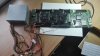
Does anyone have experience working with the Dell C8220 motherboard outside of a server unit? I tried to do a search, but only came up with one thread tagged with C8220. I picked one up recently with the hopes to use it as an overkill PC. Kind of an experiment to get my feet wet with server parts.

Here is the hardware list so far:
Dell C8220 Compute Node (Dual LGA2011)- Complete sled minus cpu's and heat sinks
2x Xeon E5-2665 CPU's - (8 cores/16 threads each - 16 cores/32 threads total)
32GB of DDR3 1066mhz Registered Ram
24/8 pin to mini 18 pin Dell C6100 patch cable
Corsair H60 Liquid cooler

Things I still need to buy:
HDD/SSD
Graphics Card
Windows 10 Pro
PCIe x16 Riser Cable (ram would be in the way if i tried to mount the graphics card to the board.)
Another Corsair H60 Liquid Cooler
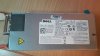
ATX Power Supply

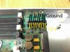
I see that a lot of people on here have experience with the C6100 and have had good luck playing with that. Specifically member S0lid (I have been using his C6100 power pinout as a rough guide). My understanding is the C8220 is just the next generation newer.

Is it doable?
Can I use this board as a dual CPU home PC, running windows 10 pro?
Anyone see any potential flaws in the idea?

I will have questions about powering the board as well as the front panel connectors in the very near future.

Anyone's help would be greatly appreciated.
 
Last edited:
  • Like
Reactions: mason736

Patrick

Administrator
Staff member
Dec 21, 2010
12,511
5,792
113
Interesting! The only time I have seen Dell C8220's installed was at the TACC Stampede supercomputer installation in Texas. I think we need pictures!
 

drabadue

Active Member
Sep 15, 2016
162
54
28
As promised, here are some pictures. Unfortunately, my apartment isn't very well lit, so forgive the lighting in some of these.

First things first, the C8220 Sled. I have already pulled the Power Distribution Board, Interposer Board, HDD Rack, and the Cooling Shroud since I will not be able to use them in my case as they wind up making the unit far too long. The board itself is right at 20" long.


The picture below shows the rear of the board with the interposer slot (right) and the gpgpu slot (left). I would like to know if i can use the gpgpu riser cable to work with my video card? Would that work? This picture also shows the front panel connector (the left one inbetween the two rear slots) and the 18 pin power connector (far right) - more on the power connector in the next post.
 

drabadue

Active Member
Sep 15, 2016
162
54
28
Next up, the power connector. From all the reading I have done, I think I may know what I need to in order to power this board.

Here is the 18 pin connector. Note the locking tab is closest to us.


And here is the wiring that plugs into that connector. Note that the locking tab is closest to us in the picture. There are 8 yellow wires, 1 purple wire and 9 black wires. *If* this board is similar to the power connector on the C6100, the yellow wires should be +12v, the purple should be a +12v SB, and the blacks should be ground. (I link my sources further down. I want to specifically thank forum member S0lid for his post with this information.)


Below is a picture of the main power harness from the Power Distribution Board to the System Board.


Here is the C6100 CPU "Patch Cable" I bought off Amazon for $14. I could have gotten it cheaper off AliExpress or eBay, but I went with amazon since it was 2 day shipping instead of 2 weeks from China.


Here is the packaging for the above Patch Cable.


Comparison showing the connectors are the same.


Here are the pinouts stolen from S0lid (a member on this forum) that I am using for a reference since it is for the Dell C6100.


I still need to check the pinout of the ATX end of the patch cable and make sure that they are corresponding with +12v, SB, and ground. As promised, here are the links to my sources on the pinouts. In the same thread, a member named RimBlock menitioned the part number for the mating 18 pin connector. "Part number is Molex microfit (3mm) 43025-1800 I believe." Both were mentioned on this thread:

C6100 xs23-ty3 Node workstation (pinouts etc)


Hopefully this helps:


The DC-DC booster I used can be found with search words "LM2577 step-up" on ebay. Yes you need multimeter for this as you need to check the Vout output so you don't burn your motherboard as the Vout ranges up to 35V! Vout is set with the variable resistor.

Remember to check out my C6100 workstation build here:
http://forums.servethehome.com/main-workstation-builds/2900-my-lian-li-a06-c6100-build.html


Worth noting that the newer boards come with the 18 pin Molex microfit power connectors and not the 12 pin.


Part number is Molex microfit (3mm) 43025-1800 I believe.

Here is one of the Taobao ATX connector sets. Note it is for the 12pin boards and the loopback wire is to turn on the PSU... permanently. With this type of setup you need to use the PSU power switch to turn it off.


@s0lid.

Do you have the part number for the 2mm and 3mm molex pins for the connectors and possibly a cheap crimping tool. Most of the hand crimpers I have seen are over US$200.

Cheers
RB


You mean minifit and microfit connectors? Yeah, you can find them pretty cheap on ebay too.
Minifit:
Male: 46012-3142
Female: 45750-3112
Microfit:
Male: 43031-0007
Female: 043030-0007

MDPC got pretty cheap minifit crimp tool (40EUR incl. VAT) and I think most of the modders use it. Haven't found cheap microfit tool yet.
 
Last edited:

drabadue

Active Member
Sep 15, 2016
162
54
28
Onto some other hardware. The CPU and RAM. I bought both of these off eBay. The RAM was listed as 16GB, but if my understanding of the model numbers is correct, there should be 32GB here. There are 4 sticks at 8GB each.


Here is a few shots of the CPU's. Xeon E5-2665's. They were the best deal I found price to performance wise, and under $100 total for the pair. I am a little worried, as it appears as though something as eaten through the coating on the heat sink down to the copper. I am not sure what caused this, or if it will be an issue. I have read that some people will "lap" their processor and cooler in order to get a better fit between the 2 to promote heat transfer. I might venture down that path if it looks like I have temperature issues as is.


For cooling, I am going with 2 Corsair H60 Liquid coolers. I currently only have one, and don't have a picture to show, but they will come into play once the try is mounted in the case.
 

drabadue

Active Member
Sep 15, 2016
162
54
28
Speaking of mounting this thing in a case, here is the case I hope to use. It is an Alienware Aurora R3. Bought it off a guy on craigslist. Came with the stock motherboard and *hopefully* a I7-2600k. I still need to verify that. No power supply, RAM or hard drive. Here is a picture of the case as I bought it.


And here it sits now, all tore down so I can clean it and get a feel for what I am working with.


Why this case you might ask? Well, I had my mind set on a Cooler Master 915F or 915R case. But they are NLA and I couldn't find a used one anywhere. When I saw this Alienware case pop up on craigslist, it looked just long enough to be able to house my motherboard. When I went to see it, I measured it out before buying it. Its going to be a very tight squeeze, but I think I can make it work. Check out the pictures below for dimensions.


Here you can see I will need to trim down the try that houses the C8220. I am also going to have to open up the area where the power supply sits in order to get the tray to slide in from the back. If all goes well, the tray will slide in and latch just like it would have in a server rack. It will be a tight squeeze, but I think it is doable.


Patrick

Administrator
Staff member
Dec 21, 2010
12,511
5,792
113
Ok I am really excited for this build now! The power was the thing that I was most worried about but it seems as though you have that figured out.

You are right on the Kingston RAM. I believe the K2 means kit of 2 and the 16GB means there is 16GB in the kit so you have 4x 8GB modules.

At some point you will want 4 DIMMs per CPU to get the maximum memory bandwidth out of the platform but for testing, using 2 DIMMs may be a good option (e.g. while seeing if you can get the board to power on.)

Great project!
 

wildpig1234

Well-Known Member
Aug 22, 2016
2,198
443
83
49
I guess you will have to drill custom holes into the case to mount the MB?

Also what's the specs on those pcie slots? just want to make sure that they have adequate wattage supply for gfx cards. are they at least 8x 2.0? will have to get riser card or ribbon cable for them...

It's workable but there's def a fair amount of custom work that will need to be done.
 

drabadue

Active Member
Sep 15, 2016
162
54
28
@Patrick - Thank you. I am hoping it all goes smooth, but I'm sure there will be some hiccups along the way. On the RAM topic, can I mix and match them on either cpu? Run all 4 of these sticks on one CPU and on the second CPU run 4 more sticks of 8GB 1066Mhz registered RAM of a different brand? I assume the number of sticks, size and speed need to all match?


@wildpig1234 - I intend to use the server tray and cut it down and then open up the power supply area on the case to accommodate loading the whole tray from the back.

Youre correct on the riser cable to get the graphics card to work. The RAM world definately be in the way. The 2 PCIe slots towards the front of the board are listed as PCIe x16 slots. I'm not sure if that answers your question. To be honest I really don't know much about PCIe slots or what 8x 2.0 refers to. (Forgive my ignorance as I will Google it shortly). I'll be running a graphics card with its own power from the power supply (hopefully an Nvidia GTX1060). Not sure if that makes a difference or not?

Custom work wise, I think it will be a fun project. I'm sure it's more work than its worth to some people, but I like the idea of having a dual CPU computer that looks just like an ordinarily PC.


Here is a link to the manuals. If you click on the link for the C8220 and go to page 231, you'll see the system board and it's connector descriptions.

http://www.dell.com/support/home/us/en/04/product-support/product/poweredge-c8000/manuals


Note that 21 and 22 are shown as PCIe x16 connectors as well as 17. The only PCIe x8 slot is the mezzanine slot listed as #2.


While I have this page out of the manual brought up, I wanted to ask about connector #3. The microSD card reader (internal USB) slot. This looks like a typical 10 minus 1 mother board connector for USB. I'm hoping it is as that would double my USB ports from 2 to 4. That logic seem sound?
 

wildpig1234

Well-Known Member
Aug 22, 2016
2,198
443
83
49
@Patrick - Thank you. I am hoping it all goes smooth, but I'm sure there will be some hiccups along the way. On the RAM topic, can I mix and match them on either cpu? Run all 4 of these sticks on one CPU and on the second CPU run 4 more sticks of 8GB 1066Mhz registered RAM of a different brand? I assume the number of sticks, size and speed need to all match?


@wildpig1234 - I intend to use the server tray and cut it down and then open up the power supply area on the case to accommodate loading the whole tray from the back.

Youre correct on the riser cable to get the graphics card to work. The RAM world definately be in the way. The 2 PCIe slots towards the front of the board are listed as PCIe x16 slots. I'm not sure if that answers your question. To be honest I really don't know much about PCIe slots or what 8x 2.0 refers to. (Forgive my ignorance as I will Google it shortly). I'll be running a graphics card with its own power from the power supply (hopefully an Nvidia GTX1060). Not sure if that makes a difference or not?

Custom work wise, I think it will be a fun project. I'm sure it's more work than its worth to some people, but I like the idea of having a dual CPU computer that looks just like an ordinarily PC.


Here is a link to the manuals. If you click on the link for the C8220 and go to page 231, you'll see the system board and it's connector descriptions.

Note that 21 and 22 are shown as PCIe x16 connectors as well as 17. The only PCIe x8 slot is the mezzanine slot listed as #2.


While I have this page out of the manual brought up, I wanted to ask about connector #3. The microSD card reader (internal USB) slot. This looks like a typical 10 minus 1 mother board connector for USB. I'm hoping it is as that would double my USB ports from 2 to 4. That logic seem sound?
I imagine the microsd reader usb so it might work. then again on my s2600cp board, the serial connector is also 10-1... probably doesn't hurt to try

you definitely need to get some pcie ribbon cables to exploit all the 4 pcie slots in the various locations on that board.
 

drabadue

Active Member
Sep 15, 2016
162
54
28
I imagine the microsd reader usb so it might work. then again on my s2600cp board, the serial connector is also 10-1... probably doesn't hurt to try

you definitely need to get some pcie ribbon cables to exploit all the 4 pcie slots in the various locations on that board.
@wildpig1234 - there is also a serial 10-1 listed as #15 - internal serial connector. So I hope that microSD works as USB.

There are also 2 SGPIO connectors and I have no idea what those do (something else for me to google).

I am also unsure of the BMC or board management controller. Hopefully that doesn't need to be hooked up or doesn't effect anything.

The rear PCIe I know I can get a Dell cable on eBay that extends it out for a gpgpu. And I'm wondering if I can use that for my graphs card? I assume it would work? The PCIe x8 is for a mezzanine card that I'm not sure I can actually use. I don't know if there is a cable to convert that into a standard PCIe slot as it looks like a proprietary connector?

Basically I'm wondering if the rear PCIe x16 gpgpu slot and PCIe x8 mezzanine slot are proprietary connectors or if they are a standard connection that's just not as popular. I'll try as post better pictures of those slots this weekend.
 

Wictar

New Member
Sep 19, 2016
27
13
3
37
Hello! I have the same motherboard Dell PowerEdge C8220. Also I have Dell D1200E-S2 power supply. I have read Mr drabadue`s article and connected motherboard to standard ATX power supply, 9 pins 12v, 9 pins - ground. System does not work, but one by one flash two green LEDs.
Can anyone suggest how to properly connect the motherboard?
 

Attachments

drabadue

Active Member
Sep 15, 2016
162
54
28
Hello! I have the same motherboard Dell PowerEdge C8220. Also I have Dell D1200E-S2 power supply. I have read Mr drabadue`s article and connected motherboard to standard ATX power supply, 9 pins 12v, 9 pins - ground. System does not work, but one by one flash two green LEDs.
Can anyone suggest how to properly connect the motherboard?
@Wictar - I am having the same issue. I got the board hooked up with the C6100 patch cable and can get the LED's to flash green on the board, but it will not power on. I do know that the LED closest to the PCI Express slots is labeled as LED17 and is for the board management controller (BMC). When the LED is flashing, the firmware for the board management controller is ready. I found that information in the owner's manual.

I also found in the owner's manual that it may take up to 2 minutes for the board actually power up. However I see nothing changing when I push the power button, or hold the power button. Even waiting a good amount of time after pushing the button, nothing seems to happen.

Something that I found to be interesting, was that when I flip the power switch off of the power supply, the blue information LED and the power button LED lights up Amber for just a brief moment.

I have enlisted help from a computer repair man that is local to me who was going to try and see what he can find out for powering the board. I imagine there has to be a "power on" or some sort of signal given by the power distribution board.

Currently, I have the purple wire just rigged up to a 12 volt signal from the power supply. I am curious if that purple wire needs a special signal or voltage?

I tried jumping pins on the front panel connector to see if I could power the board on that way. I'm not sure why you would need to, as there is a power button on the front of the board. But I had no luck trying to power it via jumper pins

Hopefully I will have more information later this week.
 
Last edited:

drabadue

Active Member
Sep 15, 2016
162
54
28
@Wictar - if you make any progress, please be sure to post back in this thread. I am eager to get this board powered up.
 

Wictar

New Member
Sep 19, 2016
27
13
3
37
@Wictar - if you make any progress, please be sure to post back in this thread. I am eager to get this board powered up.
After I bought a motherboard with Ebay, I was afraid that I could not connect the power via ATX format power supply. I ordered the original power supply Dell D1200MB-1. In the complete set there was no wires. The power supply turns on as soon as I plug it in the socket. On the power supply is written + 12V 114.17A; +12Vsb 2.5A. In internet I found that "sb" means "standby". But the problem is most likely that the motherboard needs to work through a power distribution board
 
  • Like
Reactions: wildpig1234

wildpig1234

Well-Known Member
Aug 22, 2016
2,198
443
83
49
After I bought a motherboard with Ebay, I was afraid that I could not connect the power via ATX format power supply. I ordered the original power supply Dell D1200MB-1. In the complete set there was no wires. The power supply turns on as soon as I plug it in the socket. On the power supply is written + 12V 114.17A; +12Vsb 2.5A. In internet I found that "sb" means "standby". But the problem is most likely that the motherboard needs to work through a power distribution board
This is as bad as HP and their Z8xx workstation and maybe also dell t76xx, Too much customized power connectors, etc ; (Lenovo seems to have the least amount ot customization on their WS. Wonder if thats also true on their servers)
 

drabadue

Active Member
Sep 15, 2016
162
54
28
After I bought a motherboard with Ebay, I was afraid that I could not connect the power via ATX format power supply. I ordered the original power supply Dell D1200MB-1. In the complete set there was no wires. The power supply turns on as soon as I plug it in the socket. On the power supply is written + 12V 114.17A; +12Vsb 2.5A. In internet I found that "sb" means "standby". But the problem is most likely that the motherboard needs to work through a power distribution board

The +12vSB is good to know. That means that S0lid's diagram above using the +5Vsb line from the ATX power supply and a voltage booster to bump up to 12 volts should work for standby.

The front panel connector has 12 pins on it. It is the connector towards the rear of the board. It is number 16 in the technical drawing in the posts above.

When I got my sled, there was a wiring harness plugged into that front panel connector that ran to the power distribution board. I found it interesting that all 12 pins are wired and run to the power distribution board. With that said, I assume something in that wiring mess must be what we need in order to turn the board on. I don't have any pictures currently, but I will try and find some tonight. I do know for a fact one of the pins and that 12 pin is a ground. I confirmed it with my DMM.

I wish I could get my hands on the technical drawing for the midplane the transmits power from the power supply to the power distribution board. Or even the pinout for the front panel connector.
 
Last edited:

Wictar

New Member
Sep 19, 2016
27
13
3
37
The +12vSB is good to know. That means that S0lid's diagram above using the +5Vsb line from the ATX power supply and a voltage booster to bump up to 12 volts should work for standby.

The front panel connector has 12 pins on it. It is the connector towards the rear of the board. It is number 16 in the technical drawing in the posts above.

When I got my sled, there was a wiring harness plugged into that front panel connector that ran to the power distribution board. I found it interesting that all 12 pins are wired and run to the power distribution board. With that said, I assume something in that wiring mess must be what we need in order to turn the board on. I don't have any pictures currently, but I will try and find some tonight. I do know for a fact one of the pins and that 12 pin is a ground. I confirmed it with my DMM.

I wish I could get my hands on the technical drawing for the midplane the transmits power from the power supply to the power distribution board. Or even the pinout for the front panel connector.
Have you tried to connect to the motherboard via power distibution board? Or you can not do this, because you have atx power supply? My problem is that I can not find + 12v sb contact with a multimeter. My power supply has only one contact +12v, although at the scheme on the top is written "Output +12V 114.17a; +12V sb 2.5A".
 
Last edited:

drabadue

Active Member
Sep 15, 2016
162
54
28
I do not have the Dell power supply. The problem that we would have using the Dell power supply with the C8220 power distribution board is that they both interface with a "Power Management Board" that sits in the back of the server rack unit.


Which is shown on page 287 in this link:

http://downloads.dell.com/manuals/a...ucts/poweredge-c8000_owner's manual_en-us.pdf

Both the power supply and the "Power Distribution Board" are male connectors that slide into female connectors on the "Power Management Board" (female connectors seen on the bottom of page 287 (shown above)). If we had that piece and could power the system on using all dell parts, I am sure we could figure a way to do it with the ATX power supply.


If you watch this video:


You can see that there is a small wire harness that runs from the front panel connector to the "Power Distribution Board". I imagine there is something in that wiring that will be the smoking gun we are looking for in order to get this system fired up without the "Power Management Board".