Update - switch is running totally silent using some tweaks on the information above. I only did the proof of concept and haven't soldered or cut the acrylic yet so I will update once I am completely done. I will also focus on the electrical work since the mechanical work of cutting acrylic is already shown above many times (e.g. by
@dodgy route)
Required hardware:
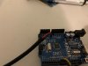
- Arduino Nano board or equivalent - This one is nice because it's small enough to fit in the original fan tray (which will no longer contain fans anyway)
- 1 x 40mm fan: I recommend the Noctua one because it comes with a bunch of handy accessories (I'm running it at 5V using the included adapter) https://www.amazon.com/Noctua-NF-A4x20-PWM-Premium-Quality-Quiet/dp/B071W93333/
- 2x 120/140/200mm fans of your choice: I used a 120mm Be Quiet and a 140mm Fractal design that I had laying around but anything that's quiet will do the trick. If you have to buy one, don't bother buying one with PWM since we won't be connecting that anyway
- 4 fan extension cables, these ones are only a couple of bucks each: https://www.amazon.com/Extension-Cooling-Compatible-Durable-Braided/dp/B082H79JTC/
- An acrylic panel (24"x18") is plenty big
- Optionally: @creidhne correctly mentioned the Molex part numbers for the plug and crimp terminals 44133000 and 43030001 (or 43030004). If you want to make this completely reversible you should probably pick some of these up. As I mentioned above I am sacrificing one fan assembly so I didn't bother.
- Some blue wire 26ish AWG wire, you can always cannibalize this from some old ethernet cable
- 4 standoffs/spacers and screws to keep your arduino board from touching the case.
- Soldering iron, basic soldering supplies, and heatshrink tubing
Note:
This mod is "reversible" if you have 2 PSUs and 2 fan modules. We will modify one of each and keep the 2nd of each untouched as spares. Also, I used an Arduino Nano, but I bought it not realizing that it was too wide. I would use the Arduino board above if I had not already bought it.
Step 1
The code provided by
@bkvamme provides a good starting point for the Arduino programming. It had some minor issues which I have resolved in the code below. Specifically, I've used 3 output pins for the tach and changed the code so that the pulse would have a 50/50 duty cycle. Program the Arduino with the code below. You can test this code by changing the duty cycle and probing your pins with a multimeter. Since it's a PWM signal, the lower the duty cycle, the lower the voltage you will read. Frequency should stay fixed at 650 Hz.
Code:
// Based on the following code.
// PWM fan control https://create.arduino.cc/projecthub/MyName1sSimon/control-pwm-fans-with-an-arduino-7bef86
// Read fan RPM https://makezine.com/2010/07/29/reading-a-pc-fan-speed-with-arduino/
// Code taken from user @bkvamme at https://forums.servethehome.com/index.php?threads/anyone-done-a-brocade-6610-fan-mod.24039/page-4
// Last Modified by Wolfcaste 2022-01-31 for use on Arduino Uno R3

unsigned int f=650; // Enter desired frequency in Hertz
double cycle_time__us = 1e6/f;
double d = 0.5; // duty cycle
unsigned int on_delay__us = round(cycle_time__us*d); // on delay in microseconds
unsigned int off_delay__us = round(cycle_time__us*(1-d)); // off delay in microseconds

void setup() {
  // put your setup code here, to run once:
  pinMode(8,OUTPUT);
  pinMode(9,OUTPUT);
  pinMode(10,OUTPUT);
  pinMode(11,OUTPUT);
  Serial.begin(9600);
  Serial.print("Frequency:");
  Serial.print(f);
  Serial.println(" Hz");
  Serial.print("Microseconds on: ");
  Serial.println(on_delay__us);
  Serial.print("Microseconds off: ");
  Serial.println(off_delay__us);
}

void loop() {
  // put your main code here, to run repeatedly:
  while(1)
  {
    digitalWrite(8,HIGH);
    digitalWrite(9,HIGH);
    digitalWrite(10,HIGH);
    digitalWrite(11,HIGH);
    delayMicroseconds(on_delay__us);
    digitalWrite(8,LOW);
    digitalWrite(9,LOW);
    digitalWrite(10,LOW);
    digitalWrite(11,LOW);
    delayMicroseconds(off_delay__us);
  }
}
Step 2
Begin by clipping the zip ties to see what wires go where in your fan assembly. Cut all wires going to the fans (cut relatively close to the fans) but leave the ones to the LED alone. I am pretty sure the 3 LED wires are for a red-green (red/ground/green) LED but honestly can't be bothered to test. Use
@creidhne 's excellent diagram below to reference the following steps.
 Step 3 - Powering the Arduino and your fans
Assuming you have standard PC fans, the first two pins (black and yellow) are GND and +12V respectively. See Noctua's diagram below. Make sure you pay attention because the color scheme is not used universally.

3.1 Cut one of your 4 pin extenders roughly in half.
3.2 Splice together a +12V coming from the fan tray (red) with wire from the second pin on the male side (likely yellow) as well as a second wire long enough to go to the VIN pin on the Arduino. Solder the other side of the wire to the VIN pin of the Arduino board.
3.3 using the same male connector from the cut off fan extender, solder together the black wire from the fan tray to the wire from first pin (almost certainly black) as well as a second wire long enough to go to the GND pin on the Arduino. Solder the other side of the wire to the GND pin of the Arduino.
Assuming you bought the Noctua fan I recommended, you should also get a handy-dandy Y splitter, which you can connect to your new harness to feed your two large fans.

 Step 4 - Making a harness to trick the ICX 6610
Alright this is the last "complicated" step.
4.1 Cut a second fan extender cable in half
4.2 Using the female side, strip the wire and solder each into 4 of the Arduino's IO pins. I used pins 8-11.
4.3 Splice together the two blue wires from the ICX 6610 fan tray with two of the wires on the male side of the connector (not important which ones we're sending the PWM signal on all 4 pins).
4.4 Splice in some additional wire (~6 inches) onto one of your two remaining pins on the male side of the connector. This is used to trick the power supply so it needs to be long enough to reach it.


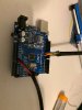
4.5 - Put Arduino board on something non-conductive (like the anti-static bag it came in) and turn on to test that everything worked. Connect to the serial port and make sure that everything works as expected and that the switch doesn't complain about failed fans.
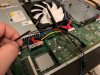
Step 5 - Modifying the power supply
IMPORTANT - MAKE SURE YOUR POWER SUPPLY IS OFF AND DISCONNECTED BEFORE WORKING ON IT AND YOU'VE LET THE LARGE CAPACITORS DISCHARGE OVER A LONG PERIOD OF TIME. THE INSIDE OF POWER SUPPLIES ARE DANGEROUS AND YOU CAN HURT YOURSELF
5.1 Open up the power supply (three screws, then it slides out).
5.2 Gently unglue the grey Formex paper (it's a fire retardant insulator so we'll want to put it back in when we're done).
5.3 Pull on the 4 rubber do-hickeys holding the Delta fan at the back of power supply in place to release the fan.
5.4 Release the fan wire from its connector at the front of the power supply.
5.5 Cut the power supply fan wire near the fan.
5.6 Feed the power supply fan wire through the grille of the power supply to the inside of the switch
5.7 Install 40mm Noctua fan in place of the Delta fan. It also comes with the same do-hickeys to hold it in place so put those in place.
5.8 Feed the Noctua fan wire through the same path as the previous delta fan. It's not quite long enough for our purposes but Noctua includes fan extensions and we have some anyways so extend it enough to go through the power supply grille. I had to pop the pins out of the connector to feed them through and put the connector back on afterwards.
5.9 Close up the power supply and put it back in place

 Step 6 - Connect the power supply wires
6.1 Cut enough of the power supply fan wire shrink tubing to reveal the blue wire. Splice that onto your long blue wire from step 4.4 above
6.2 Using your fourth fan extension cable, cut in half and splice the red and black wires from the fan power supply wires on the the male side as your did in step 3.2 (red +12V to second pin, black GND to first pin).

6.3 - Put Arduino board on something non-conductive (like the anti-static bag it came in) and turn on to test that everything worked. Connect to the serial port and make sure that everything works as expected and that the switch doesn't complain about failed fans.
 Step 7 - All the mechanical stuff
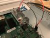
Cut holes in your Acrylic, attach fans etc. Make sure that one of the fans is above the MCU in the middle and another is above the CPU at the front. If all goes well, your result should look something like this (this is after running for almost 2 hours, but it is pretty cool in here, like 18C).
All done with mechanicals, followed posts from earlier using Acrylic panel and a dremel.


Code:
The stack unit 1 chassis info:

Power supply 1 (AC - PoE) present, status ok
        Model Number:   23-0000142-02
        Serial Number:  DVN
        Firmware Ver:    A
Power supply 1 Fan Air Flow Direction:  Front to Back
Power supply 2 not present

Fan 1 not present
Fan 2 ok, speed (auto): [[1]]<->2

Fan controlled temperature: 29.0 deg-C

Fan speed switching temperature thresholds:
                Speed 1: NM<----->78       deg-C
                Speed 2:       73<-----> 87 deg-C (shutdown)

Fan 2 Air Flow Direction:  Front to Back
MAC 1 Temperature Readings:
        Current temperature : 21.5 deg-C
CPU Temperature Readings:
        Current temperature : 22.0 deg-C
sensor A Temperature Readings:
        Current temperature : 15.0 deg-C
sensor B Temperature Readings:
        Current temperature : 27.5 deg-C
sensor C Temperature Readings:
        Current temperature : 19.5 deg-C
sensor D Temperature Readings:
        Current temperature : 21.0 deg-C
stacking card Temperature Readings:
        Current temperature : 29.0 deg-C
        Warning level.......: 83.0 deg-C
        Shutdown level......: 87.0 deg-C
Final configuration with the cover, in the rack, quiet enough that you could sleep next to it without issue.
Code:
The stack unit 1 chassis info:

Power supply 1 (AC - PoE) present, status ok
        Model Number:   23-0000142-02
        Serial Number:  DVN
        Firmware Ver:    A
Power Supply 1 Fan has failed
Power supply 2 not present

Fan 1 not present
Fan 2 failed

Fan controlled temperature: 30.5 deg-C

Fan speed switching temperature thresholds:
                Speed 1: NM<----->78       deg-C
                Speed 2:       73<-----> 87 deg-C (shutdown)

Fan 2 Air Flow Direction:  Front to Back
MAC 1 Temperature Readings:
        Current temperature : 24.0 deg-C
CPU Temperature Readings:
        Current temperature : 21.5 deg-C
sensor A Temperature Readings:
        Current temperature : 13.5 deg-C
sensor B Temperature Readings:
        Current temperature : 27.0 deg-C
sensor C Temperature Readings:
        Current temperature : 20.5 deg-C
sensor D Temperature Readings:
        Current temperature : 21.5 deg-C
stacking card Temperature Readings:
        Current temperature : 30.5 deg-C
        Warning level.......: 83.0 deg-C
        Shutdown level......: 87.0 deg-C
Boot Prom MAC : 748e.f8e7.424c
Management MAC: 748e.f8e7.424c