Adapt a HP DL380 Gen10 NVME backplane to a standard ATX power supply?

Notice: Page may contain affiliate links for which we may earn a small commission through services like Amazon Affiliates or Skimlinks.

Mithril

Active Member
Sep 13, 2019
356
106
43
Sure thing!
My Backplane is the following:

HPE Box1/2 Cage/Backplane Kit for HPE ProLiant DL380 Gen10
Article No: 826691-B21
EAN: 0725184031885, 4514953925489

The Gen9 has a different pinout (see links above).
Thanks! Do you know if gen9 and gen10 are they both Sas3?

Hmm, not encouraging that the person mentioned the gen9 one didn't work (maybe they connected 3.3V and it's acting as spindown control? )
 
Last edited:

nutsnax

Active Member
Nov 6, 2014
260
98
28
113
Hi there,
I just wanted to update my findings so far: I've tested the pins and got it working. Because it's quite similar, maybe you might have also some luck.

The other end of the power cable of the backplane is a 5-pin cable (at least in my case).
When you turn the 6-Pin End to you and with the header clip to the right hand side, the first pin on the upper right corner might be free:
View attachment 28692

The other end is a 5-pin connector. In my case, I've connected it via a custom cable to a standard ATX 4-pin molex connector on my power supply (simply cut whatever there is on the other end and apply dupont male connectors on it). For this, I've used the following pinout:

1: 12V
2: GND
3: 3.3V (or empty)
4: GND
5: 12V

With this, on my Gen10 normal Backplane, the drives are spinning and working just fine.
In my case I have installed it in a Streacom DB4 housing:
View attachment 28693
As you can see, I don't have the HPE SAS controller, so probably that's why the lovely lights aren't on. At startup, they shortly blink up in a row. Maybe there is a good Linux package to enable this feature again?
Hey thanks so much for this info!

In that picture of the connector which pin are you considering pin 1 and pin 5? I'm confused on the pin ordering.
 

Mithril

Active Member
Sep 13, 2019
356
106
43
Anyone know a mouser/digikey part number for the 6 pin end that goes into the Gen10/Gen9 backplane? Seems silly to buy a near $20 cable lol
 

tinfoil3d

QSFP28
May 11, 2020
882
407
63
Japan
Maybe it's also a silly idea but it's certainly out there to maybe just cut and solder your whatever standard cable that goes into ATX PSU to the backplane? Because that's what i sometimes do when i don't have time to look for a more flexible solution. You can always desolder as well :)
 

hmw

Active Member
Apr 29, 2019
581
231
43
Anyone know a mouser/digikey part number for the 6 pin end that goes into the Gen10/Gen9 backplane? Seems silly to buy a near $20 cable lol
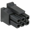
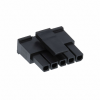
The PSU backplane is a 5pin MicroFit 3.0 connector part 0436450500

1700592541822.png

The connector that goes to the drive cage is a 6pin MicroFit 3.0 2x3 connector part 0430250600

1700592646282.png

You need to be very careful of building out your own. The ones that HP uses, can do 9A per connection. In fact HP uses 16AWG wire on these, something that I have never seen before.

If you source these on eBay or Amazon you can end up with ones doing 5A and using 22/24 AWG wire. With SAS and NVMe SSDs capable of doing 25W ~ 30W, that is a recipe for disaster.
 

nutsnax

Active Member
Nov 6, 2014
260
98
28
113
So apparently the NVME option doesn't seem to work (at least I can't make it work). Tried in a few different boxes and nothing seems to detect despite power getting to the backplane. I probably need to have some HP Tri-Mode adapter to make it work :( Oh well.
 

hmw

Active Member
Apr 29, 2019
581
231
43
So apparently the NVME option doesn't seem to work (at least I can't make it work). Tried in a few different boxes and nothing seems to detect despite power getting to the backplane. I probably need to have some HP Tri-Mode adapter to make it work :( Oh well.
Dang. Can confirm this. I just tried with a c-Payne adapter on an X11 DPH-t. The adapter does bifurcate and work when connected to slimsas 8i => slimsas 4i and a drive.

But when connecting an 8i => 8i cable to one of the cage ports - nothing happens, can’t see any drives that are in the cage

Any HP experts that can help us ?

Does the cage need an tri mode adapter?

I was looking at the PCIe riser in the HP diagram and they don’t look like they’re attached to any adapter. EDIT: here's an example HP riser. It looks like a 2 x PCIe 16x board, with the NVMe lanes directly coming off the CPU rather than any adapter ...


1702011002434.png
 
Last edited:

hmw

Active Member
Apr 29, 2019
581
231
43
This is the cable pinout I have been using:

6pin.jpg

Which corresponds to

5pin.jpg

At least for the SAS cage, using just 12V and GND seems to be enough. But for the NVMe cage, I just can't get it to work. Is the 3.3V needed for the NVMe cage? Would be interesting if it was.

The drive definitely gets power with the current layout, but I can't see anything on the NVMe side inside the cage, despite testing it in EPYC and Intel motherboards. The PCIe slot the cage is connected to is fine - it's set to x4x4x4x4 bifurcation and I've tested that drives connected to the slot appear and work fine


@ano - did you manage to measure the voltages on the HP NVMe drive cage you had in your lab?
 

hmw

Active Member
Apr 29, 2019
581
231
43
Same issue here, how sure are we that pin 3 is actually 3.3V, did anyone measure it?
A few folks on the thread talked about helping and measuring the voltages from a working HPE chassis but didn't hear anything after that. I've tried searching forums, posted here and on Level1Techs, but no one seems to know anything about these NVMe cages ...
 

nutsnax

Active Member
Nov 6, 2014
260
98
28
113
Same issue here, how sure are we that pin 3 is actually 3.3V, did anyone measure it?
I have one of these and I'm pretty sure you need a Tri-mode to run it unfortunately... maybe someone is brave enough to try these on some cheap tri-mode adapters and report back?
 

hmw

Active Member
Apr 29, 2019
581
231
43
I have one of these and I'm pretty sure you need a Tri-mode to run it unfortunately... maybe someone is brave enough to try these on some cheap tri-mode adapters and report back?
That’s weird because judging by the connections from a HP Gen9 - these would work directly from the CPU PCIe lanes and not from Tri-Mode controllers. In fact the HPE forums have techs advising that the cages *need* dual CPUs, ostensibly to provide a sufficient quantity of direct PCIe lanes
 

nutsnax

Active Member
Nov 6, 2014
260
98
28
113
That’s weird because judging by the connections from a HP Gen9 - these would work directly from the CPU PCIe lanes and not from Tri-Mode controllers. In fact the HPE forums have techs advising that the cages *need* dual CPUs, ostensibly to provide a sufficient quantity of direct PCIe lanes
No idea. I wish it worked but it hasn't for me. I've tried a number of different things with no luck. I'm keeping the cage around in case someone figures something out. I have it powered on and even soldered good power connections for it... hopefully someone figures something out.
 

Blissed

New Member
Aug 31, 2022
4
0
1
No idea. I wish it worked but it hasn't for me. I've tried a number of different things with no luck. I'm keeping the cage around in case someone figures something out. I have it powered on and even soldered good power connections for it... hopefully someone figures something out.
Did you try with 3.3V? I might just yolo pin3 with 5v. Also I very much doubt that you need a tri-mode storage controller
 

hmw

Active Member
Apr 29, 2019
581
231
43
Did you try with 3.3V? I might just yolo pin3 with 5v. Also I very much doubt that you need a tri-mode storage controller
I’ve tried with 3.3V and no luck. The only other thing I can think of is that the riser is actually PCIe 16x and not 2 * 16x. Which would mean the SlimSAS 8i connectors are in reality providing 2x lanes instead of 4x. Could explain why it doesn’t work on a “normal” SlimSAS connection
 

Blissed

New Member
Aug 31, 2022
4
0
1
I traced the pin to 4x as358a dual amplifier circuit (as358a) it looks to be part of the drive management. Each as358a has two outputs and each connects to a single drive
 

hmw

Active Member
Apr 29, 2019
581
231
43
I traced the pin to 4x as358a dual amplifier circuit (as358a) it looks to be part of the drive management. Each as358a has two outputs and each connects to a single drive
So does it take 5V and output 3.3V ?
 

Blissed

New Member
Aug 31, 2022
4
0
1
I tried 3,3V 5V 12V and pulling it to Ground and with a tri mode controller HBA-9600-24i and nothing, however I dont have the drive caddys and maybe they are required for drive detection