Fujitsu Primergy BX924 S4 blade turned into workstation - ultra low budget build

Notice: Page may contain affiliate links for which we may earn a small commission through services like Amazon Affiliates or Skimlinks.

iangreenhalgh

New Member
Nov 30, 2020
11
1
3
Hi folks

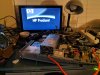
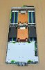
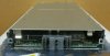
With the long winter nights approaching, I decided I needed a DIY project to keep me busy and I've long had a hankering to hack a blade into a functioning workstation. So I obtained a Fujitsu Primergy BX924 S4 dirt cheap and I already have a pair of Xeon E5-2650 V2s and a dozen 8Gb DDR3 ECC DIMMs.

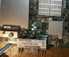
I chose the Fujitsu over the many other blades available as it has a pair of PCI-E slots (16x and 8x) which will make it much easier to add a graphics card and networking.

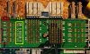
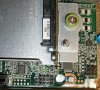
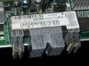
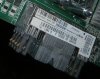
However, I have not got very far due to not being able to determine how the power pins on the back of the blade are configured - I have a suitable 1200W HP PSU and I think the blade probably requires just a +12v supply, but it's not at all obvious which pines are +12v and which are GND, even worse, I can find nothing in any Fujitsu documentation nor in any Amphenol documentation either.

Anyone got any idea how the power pins are configured on this thing?
 

Attachments

BlueFox

Legendary Member Spam Hunter Extraordinaire
Oct 26, 2015
2,106
1,528
113
You'll quickly find out that it's not worth the cost/headache of trying to make a blade functional outside of a blade chassis. It's not as simple as just giving it power. Most of the pins are used for IO and more importantly, management. I also am not sure how you'd effectively cool all of the components outside of a blade chassis either.

Given how cheap 2011 motherboards are, you're honestly just better off getting one of those. $54 shipped for one that has decent IO, including SAS: MBD-X9DRH-7F SUPERMICRO SYSTEMBOARD MOTHERBOARD LGA-2011 ATX 2x HS | eBay
 
  • Like
Reactions: BoredSysadmin

iangreenhalgh

New Member
Nov 30, 2020
11
1
3
I'm sorry, but that's not very helpful. I'm not interested in buying a different board, I have this board and all the parts I need to get it working, I simply need to overcome the roadblock of not knowing the pinout of the power pins. As for headache, I deliberately chose a very challenging project as I have built so many systems over the last 30 years all conventional porjects just aren't enough of a challenge anymore.
 

BlueFox

Legendary Member Spam Hunter Extraordinaire
Oct 26, 2015
2,106
1,528
113
I think it's probably going to be the best help you're realistically going to get with a project like this. You're unlikely to find any documentation as it's all proprietary and would be considered confidential information to Fujitsu. Amphenol just makes connectors and does not specify how they are to be used for signaling.

Why not get your multimeter out and start mapping out the traces so you can make a best guess as to what each pin is for? You'll likely need to figure out which pins control turning the thing on too as my guess is applying power won't be sufficient. There's a decent chance that's not done by pulling a pin high or low and instead is handled via the BMC, which probably means ethernet.
 

oneplane

Well-Known Member
Jul 23, 2021
846
484
63
The connector pinout is secret and custom (so no, there is no standard, not physically - hence the composable AMP connectors, you can just modify them as you see fit - and not electrically).

The power is generally a few different rails for 3v3, 5v, 12v, some newer drop one of the voltages and use on-board regulation instead.

Most other connections are management (to send special commands to then turn the node on/off, send firmware instructions so it can boot etc), and I/O like networking, storage and sensors. Sometimes they need specific clock lines as well.

Some blades are more 'complete' computers than others, but over the years more and more stuff is moved to the management chassis. Usually, the main purpose of a blade node is to have CPUs and storage, and sometimes GPUs. Everything else is not really a part of a compute node, including storage. In some cases, a USB disk is used to store something like a hypervisor or just a boot loader to boot off of the network.

You are probably never going to get this thing booting. Even if you did some measurements to find the power rails, then did the correct power sequencing, then managed to find the I2C/LPC/SPI connections, reverse-engineered the protocols the BMC uses, and send the power-on command, heartbeat and watchdog settings, you'd still have the problem of a blade not really knowing what to do after it has been started. It boots via that big interface so when nothing is connected, it can't continue, unless you like USB 2.0 speeds for your OS.

It also appears there are no schematics for any large blade manufacturer (Foxconn, Quanta etc.) and not for brands either (HP, Dell etc.). The only information that can be derived from block diagrams is that all 'normal' I/O is routed via the backplane, not anywhere else.

If you are in the mood to 'try it anyway':

- Generally, you can find out what connectors go to power by finding the 'biggest' copper connectors and traces
- Those traces will generally have current shunts to measure power draw, and they will lead to power regulators
- Power regulators have a bunch of numbers on them, you can use those numbers to find out what they are and what type of power regulation they do; if you find out that they do 12V, that's one power thing figured out, if you find others like 5V or 3.3V those are good to know about too. Other levels like core voltages (1.3, 1.2, 1.1 etc.) are probably all going to be local, not via the backplane, so if you find one of those, you'll probably be looking at a PMIC or sequencer rather than a DC-DC converter or conditioner.

Generally, blades have a few, or even a single "fat" supply like a 12V 40A connector that does it all. This means you'll need a power supply that can support 500W of 12V. A normal PC power supply cannot do that, generally. You can probably get a Meanwell 12V 40A supply, maybe a SP-480-12 or something like it.

Once you find out which one is ground and which one is positive and you just connect the power, the system might simply ignore it and do nothing. This means it needs a mating signal and sometimes a management controller as well. The mating signal is required to actually switch the device on, because if you're hot plugging blades you don't want them to power on before they are fully seated. The management controller might be required if blade system was designed to only turn on if 'allowed' by the chassis, for example to prevent overload conditions or peak power draw if an entire chassis were to power up. The controller is likely a part that you can't buy, with software you can't get.
 
Last edited:

Stephan

Well-Known Member
Apr 21, 2017
946
715
93
Germany
Hopeless (imho)... you're wasting your time trying to emulate chassis bringup. Sell the copper heatsinks for scrap value and recycle the rest. Or practice some heat gun desoldering. Always handy.
 
  • Like
Reactions: BoredSysadmin

TangTasteTester

New Member
Jul 3, 2020
15
8
3
Respectfully, you're asking people with experience what their experience is, and they reply, "Not worth the time and effort to end up with a non-functional blade."

Do with that what you will, but don't tell others they aren't helpful after asking for their input.
 
  • Like
Reactions: BoredSysadmin

iangreenhalgh

New Member
Nov 30, 2020
11
1
3
Respectfully, you are telling me it can't be done without actually knowing that it can't be done and clearly in ignorance of the fact that it HAS been done many times by people, albeit mostly using HP and Dell blades.

What I am proposing is not only possible, but has been successfully done on multiple occassions, including one thread on this very forum where several users have successfully turned Dell blades into functioning standalone computers:


There are loads of other examples of people doing the same with various models of blade - I have actually bothered to do my research into what I propose is possible and feasible, so I do feel a little annoyed that there is so much negativity here telling me it can't be done when it is highly likely, based on the success of others, that it can be done.

Do with that what you will, but don't tell me it can't be done when you don't actually know what you're talking about.
 

BlueFox

Legendary Member Spam Hunter Extraordinaire
Oct 26, 2015
2,106
1,528
113
Except we do know what we're talking about. This is exemplified by you not knowing the difference in design between the Fujitsu and the Dell system you linked. The latter is not really a blade chassis. It just shares a power supply between a few servers. All IO and disks are directly connected to the motherboard, not a control plane. They couldn't be more different.

Since you clearly know better than us, you don't need our help. Go prove us wrong.
 
Last edited:
  • Like
Reactions: TangTasteTester

iangreenhalgh

New Member
Nov 30, 2020
11
1
3
Oh dear, you really are rather condescending.

As I already said, people have done this with multiple models of blade, not just the one example I showed.

I'd bother to show you some of the many examples I found, but seeing as you already know what you're talking about, why should I bother.
 

Attachments

BlueFox

Legendary Member Spam Hunter Extraordinaire
Oct 26, 2015
2,106
1,528
113
If every single person has had a similar reply, maybe you should take that into consideration and not just ignore them because it's not the answer you wanted.
 
  • Like
Reactions: TangTasteTester

iangreenhalgh

New Member
Nov 30, 2020
11
1
3
Listen, it ISN'T helpful to tell someone something can't be done when there is a large body of proof that it can be done.

So unless you actually have something useful or constructive to contribute, stop trolling and go elsewhere.


Sean Ho

seanho.com
Nov 19, 2019
774
357
63
Vancouver, BC
seanho.com
Basically, there is no standard for power delivery or the networking/storage/bmc connections between blade and backplane; even within a manufacturer there may be major changes between generations. The examples you linked are all older gens. Without documentation, the "simplest" way may be to get a chassis and scope out the communication between the two, but of course that's often a significant cost. You've received excellent generic pointers on how to trace the power path; with mez/daughter boards removed +12v/gnd hopefully shouldn't be too hard to spot, and hopefully the other voltages are handled via onboard regulators. The blade will often need another switch or signal to actually boot; some have DIP switches to enable boot without a backplane.

You're exploring the unknown; go be a trailblazer and share what you learn!
 

iangreenhalgh

New Member
Nov 30, 2020
11
1
3
Yeah, most people have used the HP BL460C, most Gen 7s, a few Gen 6s and 8s, they are all broadly similar.

With the HP BL460C, ikt's really simple, you just hook up a 12v supply to the very obvious connectors (that have thick red and black wires leading to them, making them so obvious), then set a couple of DIP switches, hook up a KVM cable to tthe front console port and the thing will boot standalone so you can install an OS to whatever storage you have connected and you have a functioning standalone desktop computer.

This Fujitsu blade I have is hopefully similarly simple to get running, there are no DIP switches though.

Tracing the tracks to the power connectors isn't possible, or at least, I can't see how it would be. The bottom of the board is labelled with G and P pins, which I take to be Ground and Power, but that's just a guess and if not, the result would likely be the release of the dreaded blue smoke, so I hoped someone might know more than I do so I wouldn't need to guess.
 

Attachments

Last edited:

oneplane

Well-Known Member
Jul 23, 2021
846
484
63
It really depends on how much of the signalling and sequencing was moved off-board. There is no standard for it and no public data about how Fujitsu did it in their case.

Some blades are more like 'small computers' while others are closer to CPU+Memory trays. It also depends on what they were designed for; blades that were designed to run Windows bare-metal will be more like 'classic' PCs because Windows doesn't understand any other topology.
 
  • Like
Reactions: iangreenhalgh

oneplane

Well-Known Member
Jul 23, 2021
846
484
63
try looking for things that would be directly hooked up to the 12V lines, like SATA power
unless that rail comes from an on-board DC-DC supply in which case you'd be back feeding the power supply, potentially damaging it. There is no information available on the power topology. It's not all that likely that all blades run on a common regulated one-size-fits-all supply, one of them pulling on a DC rail could crash all blades; not something you'd want in a design like this.
 

cy384

New Member
Aug 19, 2022
16
12
3
cy384.com
unless that rail comes from an on-board DC-DC supply in which case you'd be back feeding the power supply, potentially damaging it. There is no information available on the power topology. It's not all that likely that all blades run on a common regulated one-size-fits-all supply, one of them pulling on a DC rail could crash all blades; not something you'd want in a design like this.
sure, don't immediately try to power it like that, just use it as a starting point to figure out how the power lines are wired up
 

iangreenhalgh

New Member
Nov 30, 2020
11
1
3
The problem is the board is very densely populated on both sides and you can't see the tracks to trace them. There is a SATA/SAS connector close to the power connector, but I can't see any tracks that could be power tracks.
 

Attachments