Poor mans 'Staggered Spin-Up'

Notice: Page may contain affiliate links for which we may earn a small commission through services like Amazon Affiliates or Skimlinks.

Lennong

Active Member
Jun 8, 2017
124
29
28
48
As title hints I am doodeling around on how to create a somewhat staggered spin-up of my 3x Supermicro BPN-SAS2-936EL backplanes with 16 disks a pop. Those 48 disks (at this time only 28) are powered by a Corsair AX1500i which obviously are struggling with deliver the amperage when all disks boot at once, even at this point with 28 of them. Real staggered spin-up is not supported with my setup so I have to go creative. My PSU can handle all 48 disks up and running, and also handle a full row (16 disks) booting up at a time no problemo. So, how to light up each row sequentially then?

As I see it I have two options;
1. Find out on how to control the backplanes with serial/signal/jumper manipulation.
2. Go 'brute force' and use a micro controller to control the boot and control the power delivery to each of the backplanes.

Serial/signal/jumper manipulation
Is it possible to utilize any of the jumpers (or other points) on the backplanes as to halt them in giving power to the disks? I know there are a few jumpers and connectors on the backplane that are made for debug, flashing and diagnostics (EPP, MDIO, EXPDGB1), could they be used to halt the power delivery to the drives? From what I can tell there is not much usable information on the net regarding the connectors and jumpers on the BPN-SAS2-936EL. Any thoughts or insights here?

Go 'Brute Force' and use a micro controller/relays
Utilizing the 'Power Good Signal' from PSU to motherboard:
The power good signal is a +5 volts signal that is generated by a switching power supply when the supply has stabilized its output voltages and passed all its internal self-tests. This is usually generated after a period of between 0.1 seconds and 0.5 seconds after turning on the power supply.
The motherboard relies on the processor timer chip which manages a reset line to the processor. As long as the power good signal is absent, the timer chip applies a constant reset signal to the processor and the computer cannot turn on. Once the power supply completes its initialization and stabilizes its outputs, the power good signal is sent to the timer chip which in turn stops resetting the processor. The processor now starts the computer boot up process and executes the code at the ROM BIOS.

So thats my go-to here.. I cut and redirect the 'Power Good Signal' (normally grey cable on ATX) to my micro controller, the 12v and 5v power to the backplanes via my beefy relays and control it all with my micro controller (Arduino, RPi or something).

So my question here is; Do my Supermicro MBD-X12SCA-5F motherboard and the On-board IPMI BMC interfere or monitor the absence or rather the presence of the Power Good Signal sent from the PSU? If I delay it for 20-30 seconds will that have any implications?
Any thoughts or insights here?


I am very grateful for any input! (Yes, tried with SM Tech support but understandably they weren't that eager to elaborate on this)

/Lennong
 
Last edited:
msg7086

Active Member
May 2, 2017
427
150
43
37
I could be wrong but 48 drives should only consumes about 900w combined. I have a NAS with 11 EXOS and 2 SSDs, and they spin up at 200w from the wall. How are you wiring the cable? I'm thinking maybe you'll need to replace the wires to a better guage to handle high current on 12v. (300w on a single 12v pin is quite a high number.)
 

Lennong

Active Member
Jun 8, 2017
124
29
28
48
I could be wrong but 48 drives should only consumes about 900w combined. I have a NAS with 11 EXOS and 2 SSDs, and they spin up at 200w from the wall. How are you wiring the cable? I'm thinking maybe you'll need to replace the wires to a better guage to handle high current on 12v. (300w on a single 12v pin is quite a high number.)
Thanks for input!

The BPN-SAS2-936EL backplanes are fed with two (2) separate Molex connected set of wires all the way back to the PSU. The Corsair AX1500i has six (6) SATA/Periphial power 'outlets' giving the backplanes 2 dedicated 'outlets' each. Cables that came with the PSU I have crimped AND solidified with connectors that translates over to the older MOLEX type onwards to the backplanes. They are all measured up and are perfectly well within acceptable specs.

It IS the overcurrent protection on the PSU that is giving me issues. I can control all ports separately on the PSU regarding over current and disable that to a certain degree (go from multi-rail to single-rail) but there is a total combined over current you can't pass, which obviously is a good thing.
Corsair AX1500i Titanium PSU Review

The spin-up load is the bad guy here, that's for sure.
 

Lennong

Active Member
Jun 8, 2017
124
29
28
48
Depending on your controller and drives: PUIS (Power-Up In Standby) could be an option.
Yes, I have looked into that as well. I am running Debian and have access to hdparm and all tools available for the dist. I did utilize hdparm before when turning off all drives that werent in use and spin-up when access (snapraid and media storage). However, the spin-ups a few times a week and temp delta kinda put me off so I stopped using it.

..but I digress; I also have a LSI HBA that sits upstreams from the backplanes / SAS expanders and I have read about some issues on LSI, LSI SAS 2008 controllers and mpt2sas driver in the perspective of booting them 'cold'.
How to fix mpt2sas "port enable: FAILED with timeout (timeout=300s)"?

Its also all SATA 'consumer' drives sitting on them so those considerations collectively kinda spooked me off it and I went back to the drawing board again. :confused:
 

Lennong

Active Member
Jun 8, 2017
124
29
28
48
I think I might have a smooth solution to this...
As I have chucked a lot of WD My Books and WD Elements I have read quite a few posts from people with chucked drives that refuse to boot up due to the 'Power Disable' feature which is controlled by P3 (Pin 3) on the Power Connector. If a 3.3v current is detected on that pin it won't boot up. It is by design to be able to remotely reboot drives without pulling them if need arise. This has led to people with older PSU's and backplanes that HAS 3.3v active to have to tape the pin over or remove completely the connector when they chuck WD drives.

The Supermicro BPN-SAS2-936EL backplanes are only fed with 12v and 5v and NO 3.3v so I have had no drama with that at all as a result. However, the P3 (Pin 3) is soldered in, exposed on the back, thus readily avalilable for me to solder on a simple 3.3v signal carrier to each slot on the backplane. It will take me a while but I will then get super granulary access to ALL drives and I can actually utilize the 'reboot' function if need arise as the drives are designed for it and the backplane also support hot plug.
The Pesky PWDIS Feature In Newer SATA Specs (not pesky for me..)

I could make groups of four on each backplane to minimize work and materials as well. To control the weak 3.3v signal is a breeze from and Arduino or RPi with a few cheap relays.

So, only thing is to check on how many of the drives has the 'Power Disable' feature activated.. From what I have read it's not all and it's random even within same batches.

EDIT: It turns out that only 3 out of 40 of my WD disks has the 'Power Disable' feature available. So that is a no go as of now. I will possibly solder in the wiring on them next time I take out the server. The SAS side of the Ultrastar got all the 'Power Disable' feature available so I might go SAS in the future anyway. I like the idea of using the intended I/O pins for this but as for now I will have to get back on the power Relay path with some kind of external controller lika an Arduino, Rpi or such. I do have a bunch of them lying around so it's just a matter of finding the stuff with proper electrical specs as it will power the backplanes. As it happends I stumbled upon a GREAT alternative yesterday but I will post that separately. :)
 
Last edited:

Lennong

Active Member
Jun 8, 2017
124
29
28
48
So, I decided to get back on the path on controlling the power delivery to each backplanes and that way having control over the peak loads on PSU. I have the code pretty much figured out as it is really trivial but not yet sure on the electrical specs.

Yesterday I found this gem:
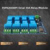
DC7-28V 5V ESP8266 WiFi 8-Channel 30A Relay Module ESP-12F Development Board | eBay
s-l1600.jpg
Specs:
1, Onboard mature and stable ESP-12F WiFi module, large capacity 4M Byte Flash
2. The I/O port and UART program download port of the WiFi module are all led out, which is convenient for secondary development;
3, The power supply mode supports DC7-28V/5V;
4, Onboard WiFi module RST reset button and a programmable button;
5, ESP-12F supports the use of development tools such as Eclipse IDE, and provides reference programs in the development environment;
6, Onboard 8-way 5V/30A relay, output switch signal, suitable for controlling the load whose working voltage is within AC250V/DC30V;
7, Onboard power indicator, relay indicator and 1 module comes with LED;
8, Onboard two shift registers 74HC595 control relay switch.

This is an industrial design to control ATM, machinery and other heavy duty stuff over WIFI and can host it's own web page to do so. A clever design.

The 'juicy' part of this board is the ESP-12F (ESP8266) module and that it is already logically and electrically incorporated in this design. That chip is a programmable microcontroller by itself and can be programmed with the Aurduino IDE Development Tool. Libraries and code examples for this extremely popular module are all over the place.

The relays are rated for 30A 30VDC (900W) which translated to 12V gives me 75A (900W). Plenty of juice for one backplane of 16 drives that pulls ~2A on each 5v and 12v lines. I will obviously use one relay for each line on each backplane.

Also the power to control both the relays and the ESP-12F (ESP8266) module comes from an external and isolated power supply. Brilliant.

Suddenly it became very easy and comfortable!;)

Cost: ~30 Euro.

A few readings with specs and relatable examples:
ESP8266 Pinout, Datasheet, Features & Applications - The Engineering Projects
ESP8266 NodeMCU Relay Module - Control AC Appliances (Web Server) | Random Nerd Tutorials


One side bonus would also be that I could wire the reset and on-off on motherboard via the relays and then control them via WIFI and the built in web page. That would give me remote ability to graceful shutdown and hard resets. The graceful shutdown by itself is a good value as I have seen too often that the IPMI/BMC can't do that properly.

I will post a follow-up once the board is here and I have something that resembles a prototype running.
 
Last edited:

mingalsuo

New Member
Dec 20, 2022
3
0
1
The relays are rated for 30A 30VDC (900W) which translated to 12V gives me 75A (900W).
Hi!

Great to find someone else also tinkering with staggered spinup.

Those relays are btw. rated for 30Vdc max or 30A max. If you put 75A through them, they'll most likely at least weld into closed position, or worse.

I was thinking about solid state relays and will research into those.
 

mattventura

Active Member
Nov 9, 2022
489
249
43
Real staggered spin-up is not supported with my setup so I have to go creative.
Might help to know why. e.g. if the reason is because the backplane spins up the drives as soon as power has applied, even if the upstream HBA hasn't actually told them to spin up, that eliminates some options.
 

Lennong

Active Member
Jun 8, 2017
124
29
28
48
Hi!

Great to find someone else also tinkering with staggered spinup.

Those relays are btw. rated for 30Vdc max or 30A max. If you put 75A through them, they'll most likely at least weld into closed position, or worse.

I was thinking about solid state relays and will research into those.
Well, from how I understand it's all about the power load (wattage) you put through them.

The relays are rated for 30A @ 30VDC (900W) which if recalculated to 12VDC gives me 75A (900W).
 

mattventura

Active Member
Nov 9, 2022
489
249
43
Well, from how I understand it's all about the power load (wattage) you put through them.

The relays are rated for 30A @ 30VDC (900W) which if recalculated to 12VDC gives me 75A (900W).
No, you have to stay under the max current, max voltage, and wattage limit if it has one.
 

mattventura

Active Member
Nov 9, 2022
489
249
43
The backplanes simply doesn't support it.
One other quick thing to check, does the backplane spin up the drives immediately upon applying power, or only once the drives are scanned? I'm assuming this is an expander backplane we're talking about.

Could you please point me to a source for that information?

..from what I have read the wattage is the culprit and you can recalculate the current and amperage based on the max wattage value.
https://relaypros.com/choosing_proper_amperage.htm
Here's a few sources:

  1. Understand Relay Specifications for your Switching System
  2. Max. switching current in relay
  3. https://media.digikey.com/pdf/other...her doc/small signal relay techincal info.pdf
From the third link:

• Maximum Switching Voltage
The maximum open circuit voltage which
can safely be switched by the contacts.
AC and DC voltage maximums will differ
in most cases.
• Maximum Switching Current
The maximum current which can safely be
switched by the contacts. AC and DC
current maximums may differ.
• Maximum Switching Power
The upper limit of power which can be
switched by the contacts. Care should be
taken not to exceed this value.


One thing to consider here - the backplane has 4 power connectors. Does it tie them together, or does it isolate them (e.g. each of the 4 connectors might be connected to 4 drives). If the former - you could run into a problem where if one relay switches slightly faster, it's going to each the current load of all 16 drives on that backplane. If the latter, it should be fine. But either way, 30A / 6 drives gives you just under 2A per drive, so it might be a non-issue.
 

Lennong

Active Member
Jun 8, 2017
124
29
28
48
Yes, they are all electrically connected but I have two relays on each backplane of 16 drives each. So thats 8 drives on each relay. I think I'll be ok.

At any rate I have managed to jack into the serial port of the backplanes and got some healthy readings and feedback from a few ideas. At last I decided to go simple;

I boot them up with only the 5v line live. All the logic is driven by that and I get all the data and status fed back from the serial port on only 5v line, no problem.

Once I staggered open up the 12v line with the burned in code in the relay the disks boot up (they do nothing with only 5v line active) and simultaniously I run a script that is parsing the /etc/fstab and wait until all the disks are recognized. Then a simple filecheck and then 'hotswap' them in with mount -a. Trivial but it works. It's done but I havent got to set it up but once I get some spare time I will lift out the server and set it up. I have the 'code' lying around in office so cant get to it as of now. It will not win contests but it works..


This is just a log from a few disks test I did:

[2022-08-17 05:53:09] : Starting spin-up sequence..
[2022-08-17 05:53:09] : Connecting to relay controller..
[2022-08-17 05:53:09] : Connecting to relay controller..
[2022-08-17 05:53:12] : Sending spin-up command to relay controller..
Backplane 1: State: On
Backplane 2: State: On
Backplane 3: State: On
Backplane 4: State: On
[2022-08-17 05:53:27] : Waiting for the detection of all disks..
[2022-08-17 05:53:27] : Waiting for the detection of all disks..
[2022-08-17 05:53:29] : Waiting for the detection of all disks..
[2022-08-17 05:53:31] : Waiting for the detection of all disks..
[2022-08-17 05:53:33] : Waiting for the detection of all disks..
[2022-08-17 05:53:35] : Waiting for the detection of all disks..
[2022-08-17 05:53:37] : Waiting for the detection of all disks..
[2022-08-17 05:53:39] : Waiting for the detection of all disks..
[2022-08-17 05:53:41] : Waiting for the detection of all disks..
[2022-08-17 05:53:43] : Waiting for the detection of all disks..
[2022-08-17 05:53:45] : Waiting for the detection of all disks..
[2022-08-17 05:53:47] : Waiting for the detection of all disks..
[2022-08-17 05:53:49] : All disks detected.
[2022-08-17 05:53:49] : Runnings filecheck on all disks..
fsck from util-linux 2.36.1
/dev/sda1: clean, 613/244191232 files, 15704577/1953506385 blocks
fsck from util-linux 2.36.1
/dev/sdb1: clean, 11/244191232 files, 15688348/1953506385 blocks
fsck from util-linux 2.36.1
TVSHOW_01: clean, 11711/244191232 files, 1616191954/1953506385 blocks
[2022-08-17 05:53:50] : Mounting all disks..

Filesystem 1K-blocks Used Available Use% Mounted on
/dev/nvme0n1p2 863984376 1587168 836013636 1% /
/dev/nvme0n1p1 497696 3484 494212 1% /boot/efi
/dev/nvme0n1p3 95241660 24 92304580 1% /config
/dev/sda1 7751272176 64944 7751190848 1% /media/disk1
/dev/sdc1 7751272176 6402014452 1349241340 83% /media/disk2
/dev/sdb1 7751272176 28 7751255764 1% /media/disk3

[2022-08-17 05:53:50] : Spin-up sequence completed!
 
  • Like
Reactions: UhClem

mingalsuo

New Member
Dec 20, 2022
3
0
1
Well, from how I understand it's all about the power load (wattage) you put through them.

The relays are rated for 30A @ 30VDC (900W) which if recalculated to 12VDC gives me 75A (900W).
Yeah, no, rated voltage dictates how well things are isolated and rated current states exactly how much current the component can take, no matter what voltage.
 

Lennong

Active Member
Jun 8, 2017
124
29
28
48
Yeah, no, rated voltage dictates how well things are isolated and rated current states exactly how much current the component can take, no matter what voltage.
Thanks for the input! ..I certainly are'nt well versed in electrical matters so I value any input in the matter. Please do tell if you find any suitable alternative to 'my' relays here. I do like the board however as it holds some good logic (Arduino compatable) and wifi module/web page with separated power lines. I will dig up the Arduino code that controls the board and *nix shell scripts I have and post theme here as well.
 

mingalsuo

New Member
Dec 20, 2022
3
0
1
Hi!

Seems like according to my PSU-specs, 10 drives and this article from 45drives, I should only have to care about power cable resistantance and how to bring the cable out of the case.

My setup will consist of two 5.25-to-5*3.5 cages on a rack shelf, UASP-converters (until changing motherboard and some external SAS HBA), bubblegum and tin foil.

It's working title is FrankenJBOD :)
 

kapone

Well-Known Member
May 23, 2015
1,103
647
113
While I applaud the effort, did you simply consider daisy chaining multiple (potentially smaller) power supplies? Server power supplies are not that expensive, used on fleabay.

The daisy chain route is how I'm driving my two Chenbro 48 bay enclosures. (and they are fully populated at this point). I junked the stock power supplies/PDB, wired in/hacked in HP PDBs and power supplies and "Add2PSU" modules that take a 12v trigger to turn on the power supply.


Each of these is an HP 460w platinum power supply, 3x per enclosure. One drives the motherboard/CPU etc, the other two power supplies (one each per expander in the Chenbro) are slaved to the main one with those Add2PSU and 12v triggers.

Been running like a champ for a few years!
 
  • Like
Reactions: Lennong