The 2-port NVMe adapter I used was this one:
https://www.amazon.com/gp/product/B09PGDMWKH which is about half price of the Supermicro card you posted.
That said, the secret sauce here is understanding how each PCIe slot maps to the CPU and chipset. As a definition, IIO stands for Integrated Input/Output and is the controller that manages traffic between PCI Express and a CPU. In our case, with the Supermicro X9SRL-F motherboard, there is only one CPU. Therefore there will only be one IIO channel to bifurcate (IIO 1). If there were two CPUs, there would be IIO 1 and IIO 2.

But what we are more interested in is how each slot maps to the PCIe controller. If we look at the lane diagram, we can see that PCIe Slot 5 maps to IOU 1A and 1B, PCIe slots 4 & 6 map to IOU ports 2A & 2B as well as ports 3C & 3D, and PCIe slots 2,3,7 map to IOU ports #A & 3B as well as 2C and 2D.

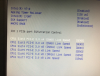
So looking at your image, your BIOS is showing that:
- IOU3 is controlling PCIe slot 2, 3 and 4
- IOU1 is controlling PCIe slot 5
- IOU2 is controlling PCIe slot 6 and 7
In order to bifurcate a PCIe lane in order to map two devices into a single slot (and each NVMe chip is a device), we have to select an x8 lane and split it into two x4 lanes.
So from your BIOS picture and the lane diagram, we could bifurcate PCIe slot 5 into two x4 slots.
This would create a new line item in the list for a port 1B at x4.
Why?
Because we know that slot 5 maps to IOU 1. It runs at x8 so it'll have only a single port. But if we split it into x4x4, then a second port is created and listed as port 1B.
We could also bifurcate IOU3 from x8x4x4 into x4x4x4x4. This would create an x4 lane for slot 2, an x4 lane for slot 3 and two x4 lanes for slot 4. When you did this, BIOS would represent the additional lane by adding a "Port 3D" line in the list.
Why?
Because we know from the lane diagram that PCIe slot 2 maps to IOU 3A, slot 3 maps to IOU 3B and slot 4 maps to IOU 3C (at x8). Splitting x8 into x4x4 would create two lanes out of one, thus creating and enabling port 3D.
So for my example I have the following hardware stuffed into the case:
2 M1015 SATA HBA adapters
2 2-port NVMe adapters
1 Mellanox ConnectX-3 fiber HBA
I needed an x8 slot for the fiber controller to perform at near max thoughput and two bifurcated x4x4 slots for the 2-port NVMe cards, so my final layout looked like this:
Slot 7 - M1015
Slot 6 - NVMe adapter
Slot 5 - ConnextX-3
Slot 4 - NVMe Adapter
Slot 3 - M1015
Slot 2 -
Slot 1 -

 731.1 KB Views: 44

