yeah only 3 phases for Vcore then. I am not familiar with FIVR. Then it's around 90A for Vcore, which gives around 150W @1.7V.
Yes I also found these mosfets are customer specifics super top secret sh*t.
Datasheet is not really important as I can monitor the mosfets overload with my infra cam. If they get hot, I know there is trouble
Also have to put a heatsink on them as they are also missing.
So next step is to find the pins for I2C. Worst case I'll have to solder directly on the IC legs, but I am sure they can be found somewhere.
Is there pinout diagram for the TPS53679? Found it
I am back on this topic after a few days off.
I found the i2c header easily, it's right next to the controller IC.
I am going to try to detect it with the EVC2 next... I don't know if a supported 85W CPU is needed or not, we will see...
Another question is regarding the BIOS flash. @RolloZ170 You said it Quanta has signed bios. I will first try all the official bioses for the normal T42S-2U servers. Those are signed, so should have no problem flashing them.... but if I need to modify anything I'll probably be in trouble, because these boards have a 256Mbit and a 512MBit flashchip on them, both in 16 pin package, so it's not a very easy soldering job and would take a looong time to write them.
But I noticed some interesting switches on the board... so my question is:
Does any of these switches allow writing of the unsigned bios?
Another question is regarding the BIOS flash.
@RolloZ170 You said it Quanta has signed bios. I will first try all the official bioses for the normal T42S-2U servers. Those are signed, so should have no problem flashing them.... but if I need to modify anything I'll probably be in trouble, because these boards have a 256Mbit and a 512MBit flashchip on them, both in 16 pin package, so it's not a very easy soldering job and would take a looong time to write them.
But I noticed some interesting switches on the board... so my question is:
Does any of these switches allow writing of the unsigned bios?
first: signed BIOS becomes corrupt by modifying, needs re-signed to become accepted by normal Update tools(IPMI,AFU)
additionaly internal BIOS protection (BIOS guard i.e.) can be in operation,
in that case also a flash of the chips with a programmer will not work.
You don't know until you try it.
I am back on this topic after a few days off.
I found the i2c header easily, it's right next to the controller IC.
I am going to try to detect it with the EVC2 next... I don't know if a supported 85W CPU is needed or not, we will see...
Another question is regarding the BIOS flash. @RolloZ170 You said it Quanta has signed bios. I will first try all the official bioses for the normal T42S-2U servers. Those are signed, so should have no problem flashing them.... but if I need to modify anything I'll probably be in trouble, because these boards have a 256Mbit and a 512MBit flashchip on them, both in 16 pin package, so it's not a very easy soldering job and would take a looong time to write them.
But I noticed some interesting switches on the board... so my question is:
Does any of these switches allow writing of the unsigned bios?
Got one step further again today....
I got EVC2SE working (I spent about 2 hours trying to get it working under Win7 without luck, so I moved on to a Win10 laptop.)
Finally VRM Controller detected and guess what.... it's configured at 105A ICC_Max! LOL
Immediately set it to 228A, but could not test it yet, because my non-ES CPUs are at the customs since days...
I'll report back in a few days... or might try modded BIOS with ES if I would have time....
sure I do not mean that,
you can choose 190/228/255Amps with my script FOR YOUR INFO
but still 190A is standard setting in supermicro X11DPL-i ( max. 2x 140W )
sure I do not mean that,
you can choose 190/228/255Amps with my script FOR YOUR INFO
but still 190A is standard setting in supermicro X11DPL-i ( max. 2x 140W )
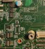
Ah ok yes. Doesn't really matter what I set until i test some 125-150W cpus with infra termometer on that 3+1 phase VRM.
Any idea whats the spec for those top secret mosfets?
Edit: btw it would be a wild idea to rebuild the missing phases?
Vrm controller would need reprogramming of the number of phases also? Or it would automatically control the extra phases?
Doesn't really matter what I set until i test some 125-150W cpus with infra termometer on that 3+1 phase VRM.
Any idea whats the spec for those top secret mosfets?
first: signed BIOS becomes corrupt by modifying, needs re-signed to become accepted by normal Update tools(IPMI,AFU)
additionaly internal BIOS protection (BIOS guard i.e.) can be in operation,
in that case also a flash of the chips with a programmer will not work.
You don't know until you try it.
I've been looking at modded BIOS writing on servers that has signed BIOS. I found some methods involving old version of AfuWin (or AfuEfi) and the /GAN option.
Any chance that this would work on a Quanta server?
Another Method would be flashing thru SPI. Any chance here to bypass signature check?
Guide in the Guide:
modify X11SPL-F & X11SPM-(T)(P)F BIOS 3.9 & 4.0 to support 255Watts
download the BIOS 3.9 or 4.0 from supermicro. download HxD or use your favorite Hex Editor and open the BIOS file.
( A5 hex = 165 dec. / FF hex = 255 dec. )
X11SPL BIOS 3.6
( this is only correction of ProjectPeiDriver.ffs checksum )
search for "26 22 9C 73 64 32 54 44 99 1C 8D C4 4A 73 D6 AF C3 23"
replace with "26 22 9C 73 64 32 54 44 99 1C 8D C4 4A 73 D6 AF C3 6F" X11SPL BIOS 3.9
( this is only correction of ProjectPeiDriver.ffs checksum )
search for "26 22 9C 73 64 32 54 44 99 1C 8D C4 4A 73 D6 AF 62 6C"
replace with "26 22 9C 73 64 32 54 44 99 1C 8D C4 4A 73 D6 AF 62 B8" X11SPL BIOS 4.0
( this is only correction of ProjectPeiDriver.ffs checksum )
search for "26 22 9C 73 64 32 54 44 99 1C 8D C4 4A 73 D6 AF 81 7A"
replace with "26 22 9C 73 64 32 54 44 99 1C 8D C4 4A 73 D6 AF 81 C6"
X11SPM BIOS 3.4
( this is only correction of ProjectPeiDriver.ffs checksum )
search for "26 22 9C 73 64 32 54 44 99 1C 8D C4 4A 73 D6 AF 82 9D"
replace with "26 22 9C 73 64 32 54 44 99 1C 8D C4 4A 73 D6 AF 82 E9" X11SPM BIOS 3.5
( this is only correction of ProjectPeiDriver.ffs checksum )
search for "26 22 9C 73 64 32 54 44 99 1C 8D C4 4A 73 D6 AF 82 65"
replace with "26 22 9C 73 64 32 54 44 99 1C 8D C4 4A 73 D6 AF 82 B1" X11SPM BIOS 3.8a
( this is only correction of ProjectPeiDriver.ffs checksum )
search for "26 22 9C 73 64 32 54 44 99 1C 8D C4 4A 73 D6 AF C3 EE"
replace with "26 22 9C 73 64 32 54 44 99 1C 8D C4 4A 73 D6 AF C3 3A" X11SPM BIOS 3.9
( this is only correction of ProjectPeiDriver.ffs checksum )
search for "26 22 9C 73 64 32 54 44 99 1C 8D C4 4A 73 D6 AF 62 4A"
replace with "26 22 9C 73 64 32 54 44 99 1C 8D C4 4A 73 D6 AF 62 96" X11SPM BIOS 4.0
( this is only correction of ProjectPeiDriver.ffs checksum )
search for "26 22 9C 73 64 32 54 44 99 1C 8D C4 4A 73 D6 AF 81 7E"
replace with "26 22 9C 73 64 32 54 44 99 1C 8D C4 4A 73 D6 AF 81 CA"
X11SPL / X11SPM all BIOS
search for "6C 68 A5 00 00 00 68"
replace with "6C 68 FF 00 00 00 68"
X11SPL / X11SPM all BIOS
search for "FB B9 A5 00 00 00 5E"
replace with "FB B9 FF 00 00 00 5E"
save as "BIOS_X11SPL-096E_20230315_3.9_255W.bin" respective "BIOS_X11SPL-096E_20230620_4.0_STD.bin"
save as "BIOS_X11SPM-095D_20230315_3.9_255W.bin" respective "BIOS_X11SPM-095D_20230620_4.0_STD.bin"
its works now, here is a proof View attachment 26864
The Thermal Design Current(TDC) of those processors is 255A, std.default is 228A(TDP=165-205W) and lower.
You can see this TDC value with AIDA, HWinfo does not show this parameter or as PL4. View attachment 26505
actualy there are three ways to do this, except for boards with PXE1610C ( only supported by MCP2221a )
1) MCP2221a (Adafruit)
i made a c# console app for automatic programming ( MCP2221a_iccmax_FF(18122023).7z ) vrm TPS53679/PXE1610C/MP2955A
(if you have concerns using my exe on your system: use iLSpy to see/get the c# sourcecode of them, and recomplie your own)
typical usage(cmd window)
"MCP2221a_iccmax_FF -MP2955A 20"
or
"MCP2221a_iccmax_FF -PXE1610C 60"
or
"MCP2221a_iccmax_FF -TPS53679 58"
2) only MP2955A used in
X11SPM-T(P/F)
X11DPi-N(T) rev.2.x and up
and others
you need I2C interface MPS EVKT-USBI2C-02:
MPS Software V4.5.11 ( if you don't get the Software with MP2955A support, PM me )
3) only for mboards use MPS MP2955A and TI TPS53679
Note:
If you don't have suported CPU(s) to do the modification try it with the high TDC CPU(s), mostly this works,
the system just turns on but you will get no display, the CPU(s) reset is helt low.
you can do now the VRM modification. With supported CPU(s) enter the BIOS and start modifying.
Do not power the X11SPM, install a CPU and connect the EVC2SX or MCP2221a header with a 3 wire Cable to the JVR1 header of the X11SPM View attachment 26506
Connect the EVC2SX with the USB Cable to your PC and start the EVC2 Software.
Now you can power on the X11SPM, click on I2C1 and click "Find Devices" the MP2955A should be found and visible under I2C1.
Click on this entry to open the Device: View attachment 26507
click "Monitoring" to see the value of ICC_MAX.
you can select the standard or max. ICC_MAX in the dropdown menu. View attachment 26508
STORE_USER_ALL is to save the setting permanent. View attachment 26509
With a click at "Apply changes" the new ICC_MAX is written and if you choosed "yes" for STORE_USER-ALL this setting is copied in the NVM of the VRM controller. View attachment 26510
If you have any questions, ask me.
X11DPi-N(T):
i have successfully modified a X11DPi-N(T) rev. 2.01A to run TDC 255A TDP 240W SKUs(i.e. Amazon AWS customs)
With CPU in both sockets installed the procedure is similar than decribed above, you will see two MP2955A (adr 0x20 and 0x21)
Remove the JVRM1/2 jumpers and connect the I2C :
JVRM1 pin2 = SCL
JVRM2 pin2 = SDA
USB2/3 pin7/8 = GND (or any other GND pin)
X11SPL-F X11SPi-TF X11DPL-i 11DPH-i :
we have successfully modified a X11SPL-F (adr 0x58), X11SPi-TF (adr 0x58), X11SPH (adr 0x58), X11DPL-i (adr 0x58 / 0x60) and X11DPH-i (adr 0x58 / 0x60) to run TDC 255A TDP 240W SKUs(i.e. Amazon AWS customs)
With CPU in both sockets installed the procedure is siliar than decribed above, you will see one or two TPS53679
X11SPL-F & X11SPM-(T)F (may block TDP higher than 165W, Guide to make BIOS 3.8a with 255W support )
X11SPi-TF, X11SPH-nCT(P)F
JVR(M)1 pin1 = SCL
JVR(M)1 pin2 = SDA
JVR(M)1 pin3 = GND
X11DPi: View attachment 26511View attachment 26512
Remove the JVRM1/2 jumpers and connect the I2C :
JVRM1 pin2 = SCL
JVRM2 pin2 = SDA
USB2/3 pin7/8 = GND (or any other GND pin) X11DPH:
Remove the JVRM1/2 jumpers and connect the I2C :
JVRM1 pin2 = SCL
JVRM2 pin2 = SDA
T-SGPIO1 Header Pin3/6 = GND (or any other GND pin) X11DPL-i: (set to 228A to run up to 205W SKU)
Remove the JVRM1/2 jumpers and connect the I2C :
JVRM1 pin2 = SCL
JVRM2 pin2 = SDA
USB2 Header pin7/8 = GND (or any other GND pin)
Finally got it working.
Both 85W< TDP and ES CPUs in the Quanta crippled server. Currently running 135W QL1L 20Core CPUs in a node.
Next step is to test out my custom VRM heatsinks, etc.
BTW I spent days on trying to flash with Afu, FPT, Yafuflash, etc.... but for the BIOS region nothing worked, only when I finally desoldered the SOP16 eeprom and flashed it manually. Surprisingly it booted up with the modded BIOS and working fine (despite having all Boot Guard/ Bios Guard/National Guard enabled, they don't bother with the fact that I modified the signed BIOS).
but for the BIOS region norhing worked, only when I finally desoldered the SOP16 eeprom and flashed it manually. Surprisingly it booted up with the modded BIOS and working fine.
Thanks again to @RolloZ170 , @PandaChan and @jason879 for the helpful information, which I could successfully apply to a T7820/8272CL combo.
Now, I we have success confirmations for the T7820/T7890 for the:
8222CL
8251C
8259CL
8272CL
(all with updated VRM limit and latest Bios - remember to check Bios before changing the CPU)
I think no confirmation (or negative result) has been posted so far for the 8275CL. If anyone has tried it with/without success, that would be interesting information. But this CPU is also relatively expensive - maybe it is compatible with some platform ootb.
For the four working CPUs above, I would be interested in maximum memory clock achieved; my understanding is that Cascade Lake should support 2933 MHz, but I think I have seen only 2666 MHz for these "in the wild".
(Observed on my T7820 with 2933 MHz DIMMs running at 2666 MHz; Ebay sellers' CPU tool screenshots seem to show 2666 MHz for all four CPUs, while Wikipedia seems to suggest 2933 MHz for the 8251/8251C and 2666 MHz for the others.)
What are your observations regarding memory clock?
(When responding, please differentiate whether you refer to use in a T7820/T7920 or use in some other board/platform.)
CPU tool screenshots seem to show 2666 MHz for all four CPUs, while Wikipedia seems to suggest 2933 MHz for the 8251/8251C and 2666 MHz for the others.)
This site uses cookies to help personalise content, tailor your experience and to keep you logged in if you register.
By continuing to use this site, you are consenting to our use of cookies.
")
 887.2 KB Views: 20