Need help to 3D print 1U Supermicro X9 i/o shield

Notice: Page may contain affiliate links for which we may earn a small commission through services like Amazon Affiliates or Skimlinks.

epicurean

Active Member
Sep 29, 2014
785
80
28
I need help from anyone here who is familiar with Fusion360 to help edit this f3d file so that I can use it in a 1U chassis, my the X9DRD-LF motherboard. I only know how to print stl files on my 3d printer, no idea how to edit with Fusion360

have changed the extension to pdf so i can upload it.

Thanks very much

I believe the i/o shield looks like this uploaded jpg
 

Attachments

Markess

Well-Known Member
May 19, 2018
1,162
780
113
Northern California
Are you familiar with any other editing tools, like Tinkercad (which is free and web based)? A 1U compatible blank I/O shield file for the CSE-815 is available in an STL format here:

Supermicro CSE-815 Server IO Shield Blank by DanAndersen

Unfortunately, even though the author (not me) shows a picture of the actual I/O shield you want to model, the STL file is only the blank one.

This I/O shield (for an X10SLM-F) looks to have similar, if not the same, component spacing but is a standard height (not 1U) shield. I'd think it would be possible to merge the two files and get to what you want?

SuperMicro IO Shield MCP-260-00073-0N for X10SLM-F by gjnijenhuis
 

epicurean

Active Member
Sep 29, 2014
785
80
28
@Markess Thank you but unfortunately I have zero experience using stl editing tools. I do have Fusion360(education) installed but never got round to learning it. How do I merge the 2 files (if it can be explained to a noob like me)?
 

Markess

Well-Known Member
May 19, 2018
1,162
780
113
Northern California
@Markess Thank you but unfortunately I have zero experience using stl editing tools. I do have Fusion360(education) installed but never got round to learning it. How do I merge the 2 files (if it can be explained to a noob like me)?
I can set a file up for you to try. But, since I no longer have one of those motherboards or a CSE-815, I'd need you to give me some measurements to help me with vertical placement of the component openings:

With the motherboard in place in the chassis, could you measure the vertical distance between the center of the I/O plate mounting screw holes in the chassis (the ones near the top of the opening on the left and right sides) and the vertical center of the Serial and VGA connectors for their respective sides? With those measurements, I can put together a file for you faster than it would take me to explain it ;).

I think you'd need to PM me with your email address to email the file, as I don't think I can attach an STL file to a post.

If you have access to a 3D printer, knowing how to use a simple program for designing basic STL files for print is a very good idea. Starting off with a really full featured modeling program like Fusion360 will be very difficult. A simple beginner friendly free program like Tinkercad (also from Autodesk, the company that makes Fusion360) may be a better option to begin with. www.tinkercad.com Tinkercad cant do as much as Fusion, but because of that the menus are much simpler and easy to learn.

There's numerous tutorials on the web for Tinkercad, via YouTube and other sites. Because its free and in widespread educational use, you can easily find tutorials for anything you want, or can't remember how, to do. i.e. Google "Create hole in Tinkercad" etc
 
  • Like
Reactions: RimBlock

epicurean

Active Member
Sep 29, 2014
785
80
28
@Markess[/USER], I will be grateful for any lessons you have for me to learn , if you willing to teach. I only have Fusion360 installed - is that technically too challenging ? IF so, I will download tinkercad.

Will try to get you the dimensions when I get into the office where the printer AND the 1U case resides. The 1U case is not a supermicro case but I think it conforms to a generic 1U io shield sizes for the back

Update - the io plate is different with no screw holes. Please see pictures of old io plate for previous motherboard. Metric measurements

W io plate.jpg
L io plate.jpg
1U back.jpg
 
Last edited:

RimBlock

Active Member
Sep 18, 2011
837
28
28
Singapore
Ok, so some thoughts.

Can you not cut some holes out of the squares section to allow connectors through or are you looking to keep the io plate for the other board.

I have a chat with Taknet as they do distribution and retail for all Supermicro items in SG. They could probably sort you out with a plate without the international shipping.

If you really want to go the 3D print route then one word of caution is that the IO plates are made of metal in that design as the edges provide some springiness in order to grip the edges of the hole. This would be fairly difficult to do with hard materials like ABS / PLA. This is even worse if the plate is pushed in from the back outside rather than being clamped between the rear wall of the chassis and the motherboard as they are in most chassis as if not tight enough it could just fall out. On the plus side, if it is too tight you can just file it down if the walls of your print allow.

If you still really want to go this route, I use Design Spark from RS-Online which is also free. It is fairly simple with some powerful features if you want them. There is also community support and manuals which are pretty good.

Make sure you also have a slicer available to turn the object in to printing layers. I use Simplify3D but this is paid for software.

You need to measure where the holes need to be and can use construction lines to mark out without actually affecting the object. Map the shape for the holes measurements with construction lines, then create the shape with lines / arcs / circles. When done select it and use the 'pull'tool to pull the shape through the plate which should subtract it.

Depending on your printers accuracy, settings and material you may need to +/- some mm or fractions there of to get a fit.
 
  • Like
Reactions: Markess

Markess

Well-Known Member
May 19, 2018
1,162
780
113
Northern California
I will be grateful for any lessons you have for me to learn , if you willing to teach. I only have Fusion360 installed - is that technically too challenging ? IF so, I will download tinkercad.
I don't know your level of expertise, so I don't want to say Fusion 360 is too challenging. I'm just saying it has many many many features that you don't need at this point, so it may be difficult to sort through the menus/options to find the ones you do need. I mentioned Tinkercad primarily because it is an Autodesk product, the same as Fusion360. Also, its free web based service. You don't need to download it. Just sign in with a browser.

I've not used the program that @RimBlock mentions. But, RS is a great company, and has an extensive maker community that uses their products. They have a lot of products (hardware and software) targeted at getting new makers up and running, so this program may be just what you need. I looked briefly and it seems like its got more features than Tinkercad without being overly complex.

Update - the io plate is different with no screw holes. Please see pictures of old io plate for previous motherboard. Metric measurements
IF I understand correctly, the two I/O Shield pictures are of the one that came with the case? The last picture is of the motherboard in the case itself? If you can confirm that, I'll put a model together for you

If you really want to go the 3D print route then one word of caution is that the IO plates are made of metal in that design as the edges provide some springiness in order to grip the edges of the hole. This would be fairly difficult to do with hard materials like ABS / PLA. This is even worse if the plate is pushed in from the back outside rather than being clamped between the rear wall of the chassis and the motherboard as they are in most chassis as if not tight enough it could just fall out. On the plus side, if it is too tight you can just file it down if the walls of your print allow.
@RimBlock is exactly correct! I don't even bother trying to make a plate that "Snaps In". I try to make them a snug fit, by design if I'm lucky, and by filing them down if I'm not. Then I secure them with a bead of hot glue. The glue dries clear and can be easily peeled away if I need to remove the plate later. Silicone sealant can work too. You just don't want to use anything permanent that can't easily be peeled away. On one full sized case, I set up the printer to print with a skirt. After printing, I left the skirt on, which gave me a surface to adhere to when I inserted the I/O shield into the case from the inside.

Can you not cut some holes out of the squares section to allow connectors through or are you looking to keep the io plate for the other board.
This is usually the easiest. Not as pretty, and doesn't make use of any crazy design skills. But usually the easiest.
 
  • Like
Reactions: RimBlock

epicurean

Active Member
Sep 29, 2014
785
80
28
@Markess, Yes, the pictures are the ones of the existing io plate, and also the 1U case. Thanks so much for helping me put a model together.
I probably should find online lessons (with all the lockdown anyway) on a simple creation and editing of 3d models for printing. So Tinkercad is easy to use?
 

epicurean

Active Member
Sep 29, 2014
785
80
28
@RimBlock Thanks for the heads up with Taknet. I suspect they are all closed now due to the lockdown in SG. I do have PETG which is somewhat flexible, would that be a better alternative to PLA? I am still using Cura, and of late have been leaning towards trying out Prusaslicer but I hear each slicer behaves differently even with the same code on our printer
 

RimBlock

Active Member
Sep 18, 2011
837
28
28
Singapore
Then I secure them with a bead of hot glue. The glue dries clear and can be easily peeled away if I need to remove the plate later. Silicone sealant can work too. You just don't want to use anything permanent that can't easily be peeled away. On one full sized case, I set up the printer to print with a skirt. After printing, I left the skirt on, which gave me a surface to adhere to when I inserted the I/O shield into the case from the inside.
Good call :).
 

RimBlock

Active Member
Sep 18, 2011
837
28
28
Singapore
@RimBlock Thanks for the heads up with Taknet. I suspect they are all closed now due to the lockdown in SG.
Spoke to them yesterday so they are open but maybe at reduced capacity / walk-in service.

I do have PETG which is somewhat flexible, would that be a better alternative to PLA?
PEGT is what they make the plastic soft drink bottles out of and is pretty flexible when thin but not sure how flexible it remains when layered up in thickness. Better than ABS and PLA most likely.

Putting a TPU / TPE (Ninjaflex etc) 'skirt'around the part that grips the hole would also be a possible option if you really wanted to over engineer a solution o_O. Problem with these materials with a softer shore rating (Ninjaflex is like a car tyre rubber) is that they are harder to print. I have a Flexion extruder on my 3d printer for this very reason. It was expensive but it has not let me down.

I got a QIDI Tech 1 a number of years ago (to replace my CNC router which was big, messy and very noisy - especially for home). Very happy with it. Their newer machines look pretty decent too.

I have also added a maghold heated printer bed (YouTube link) which has magnets in the bed and a sprung steel plate that you print on. You can then just take the play of and twist it for the print to 'pop'off. It is really good but seem it is not sold anymore. The only problem with it is that in SG's humidity, the sprung steel plate tends to rust. Luckily it is only surface rust and a quick scrub with a kitchen pot cleaner and it is good as nw and whats more you get a lovely patina ;).

My printer gets quite light use and TBH the biggest issue I tend to find is the Teflon guide tubes seem to have lost their slippyness. Cleaning with soapy water and then adding a tiny bit of dish washing soap helps short term but I need to replace them.
 
Last edited:

Markess

Well-Known Member
May 19, 2018
1,162
780
113
Northern California
@epicurean . I put something together for you, please PM me an email address and I'll email you the file.

I made a simple flat plate. Because I don't have the exact case and motherboard in front of me, or exact measurements of the I/O Shield, like detailed measurements of the "lip" that the metal shields have to snap into place and etc. trying to replicate that just wouldn't work.

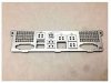
I started with a 1U backplate I found online at Thingiverse.com for the A1SAI/A1SRI motherboards. These boards use the same exact I/O shield part number as your board. They just make use of different hole knockouts.

1U IO Shield/Backplate for Supermicro A1SAI/A1SRI Mainboards by 3DMK

The overall size of this plate didn't match the measurements of yours though, and the height of the component openings was different. So I adjusted for that. In one of your photos of the I/O shield that came with the case, it appeared that the vertical center of the lowest USB opening was ~10mm, so I adjusted the height of the component openings based on that.

Lastly, the model at the link above was quite thick, 1.5mm. I made this one 0.5mm, so to be closer to the thickness of the metal version. I understand PET-G can go down to 0.2mm but at that thickness, successful prints are difficult.

As for learning, the program @RimBlock recommends looks to have more features than TInkercad, but not so many that it will be overwhelming. My preference for Tinkercad is mostly due to it being online. I do educational training for kids at their school classrooms for multiple schools in the region. Not having to have kids/teachers load a program on classroom computers when we visit is a big plus. But, since you have your own computer, installing an application isn't an issue.

To get up and running on 3D prints for your projects, you may want to spend a bit of time browsing/searching file library sites like thingiverse.com. For lot of projects, like this I/O shield, you will often find a file you can modify for use, or if you are lucky, one already designed for your specific purpose. Many sites, again like Thingiverse, make the files freely available. There's a provision to provide a payment of your choice to the creator if you wish, but its optional. Starting with a file that's close to what you need can save you some time.
 

epicurean

Active Member
Sep 29, 2014
785
80
28
@Markess
Thanks ! you have PM

The QiTi Tech looks nice but out of my budget. I have a modified Anycubic Linear Plus ( BMG extruder, E3DV6 hotend, BTT SKR 1.3 board with TMC2209 drivers). Print volume is a little less than what I like, and I am actully mulling over build a corexy printer with a bigger xy print volume. Any suggestions? Hypercube Evolution, voron, seckit,vking - so many options that it confuses me.