Hello all! This is my first post, but I've been a user of this forum since years learning a lot from this awesome comunity.
Recenlty I bought a Gigabyte MU92-TU1 motherboard for my new lab environment. The reason why I chose this motherboard is because comes with 16 DIMM slots and I reuse my 16x32GB sticks (2933MHz) from my previous system on this new one.
The point is the BIOS on this motherboard and generaly in motherboards from Gigabyte (as far as I know), are hidden in BIOS menus the PCIe bifurcation options. Not because the hardware doesn't support it, but for any reason this vendor prefer to not display that feature.
I have some Samsung 980 Pro NVMe sticks and I want to use it with this motherboard with a PCIe adapters like I've been using since last year and a half.
I was thinking also to replace the PCIe adapter for a NVMe RAID adapter solution, like the HighPoint SSD7505, but unfortunely this is not compatible with VMware ESXi which will be running on this system.
A few weeks ago I seen this post from @andrewbedia explaining how to modify and flash a BIOS Mod for a Gigabyte Xeon motherboard from previous generation (1st and 2nd Xeon Scalable) and I take it from reference to modify BIOS for my motherboard.
The guide works and the tools user permit me to modify the .bin and .rom files, but at the time to flash it... didn't work.
I try many times and a lot of tools and ways to flash it.
The tools used are; afudos, afuwin, AMI Setup IFR Extractor, FPT and other that I don't remember. In all cases I get a error showing the BIOS is write protected.
As I can find during my troubleshooting process is when BIOS is modified, the signature in .rom file cannot be saved by AMIBCP and on .bin files sems the same. I thiks is the vendor or AMI BIOS signature.
The BIOS protection I don't know from where comes, if is from Intel ME (I read it about in other articles and forums Googling it) or if it's another kind of protection.
At this point and whith the imposibility to do it by software flashing, I'm thinking to flash the BIOS chip from hardware tools like CH341A or similar.
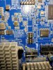
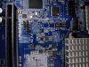
My surprise was when I see the BIOS chip is type SIOC16 or SOP16, the model is MX25L51245GMI-08G.
I didn't see any reference about how to flash it or the constrains for flashing this chip in this motherboard or others with the same BIOS chip.
I ordered in Aliexpress 2 chips and a clip SOP16 to try to flash it by myself, but I don't know if the CH341A is the apropiated Hardware tool to flash those chips or I have to use other for that. I want to test as many flashes as I can to try if I the BIOS Mod can be written in the new chips and then try in the motherboard chip, but honestly I don't know if this is the correct way to do it or instead of thar, better do a chip replacement (unsoldering the original) with the new one flashed with BIOS mod.
Ofcourse I prefer to not do any hardware manipulation (unsoldering) on a new motherdoard, at least if there is no garantee if that would work.
Anyone here have experience with the same or similar problems and how to resolve it?
Many thanks!
Recenlty I bought a Gigabyte MU92-TU1 motherboard for my new lab environment. The reason why I chose this motherboard is because comes with 16 DIMM slots and I reuse my 16x32GB sticks (2933MHz) from my previous system on this new one.
The point is the BIOS on this motherboard and generaly in motherboards from Gigabyte (as far as I know), are hidden in BIOS menus the PCIe bifurcation options. Not because the hardware doesn't support it, but for any reason this vendor prefer to not display that feature.
I have some Samsung 980 Pro NVMe sticks and I want to use it with this motherboard with a PCIe adapters like I've been using since last year and a half.
I was thinking also to replace the PCIe adapter for a NVMe RAID adapter solution, like the HighPoint SSD7505, but unfortunely this is not compatible with VMware ESXi which will be running on this system.
A few weeks ago I seen this post from @andrewbedia explaining how to modify and flash a BIOS Mod for a Gigabyte Xeon motherboard from previous generation (1st and 2nd Xeon Scalable) and I take it from reference to modify BIOS for my motherboard.
The guide works and the tools user permit me to modify the .bin and .rom files, but at the time to flash it... didn't work.
I try many times and a lot of tools and ways to flash it.
The tools used are; afudos, afuwin, AMI Setup IFR Extractor, FPT and other that I don't remember. In all cases I get a error showing the BIOS is write protected.
As I can find during my troubleshooting process is when BIOS is modified, the signature in .rom file cannot be saved by AMIBCP and on .bin files sems the same. I thiks is the vendor or AMI BIOS signature.
The BIOS protection I don't know from where comes, if is from Intel ME (I read it about in other articles and forums Googling it) or if it's another kind of protection.
At this point and whith the imposibility to do it by software flashing, I'm thinking to flash the BIOS chip from hardware tools like CH341A or similar.
My surprise was when I see the BIOS chip is type SIOC16 or SOP16, the model is MX25L51245GMI-08G.
I didn't see any reference about how to flash it or the constrains for flashing this chip in this motherboard or others with the same BIOS chip.
I ordered in Aliexpress 2 chips and a clip SOP16 to try to flash it by myself, but I don't know if the CH341A is the apropiated Hardware tool to flash those chips or I have to use other for that. I want to test as many flashes as I can to try if I the BIOS Mod can be written in the new chips and then try in the motherboard chip, but honestly I don't know if this is the correct way to do it or instead of thar, better do a chip replacement (unsoldering the original) with the new one flashed with BIOS mod.
Ofcourse I prefer to not do any hardware manipulation (unsoldering) on a new motherdoard, at least if there is no garantee if that would work.
Anyone here have experience with the same or similar problems and how to resolve it?
Many thanks!
Attachments
-
 676.8 KB Views: 14
 -
 611.4 KB Views: 14

