supermicro 846a backplane repair help

Notice: Page may contain affiliate links for which we may earn a small commission through services like Amazon Affiliates or Skimlinks.

nkw

Active Member
Aug 28, 2017
136
48
28
Sounds like the right plan to me. Here is the same area on a brand new 846A:
 

Attachments

pricklypunter

Well-Known Member
Nov 10, 2015
1,704
513
113
Canada
Not an oscillator, just a 16Mhz crystal. The "oscillator" part is built into whatever it's connected to, in this case the hotswap/ backplane controller chip. It also has a couple of coupling compensation capacitors, usually one on each leg to ground. Get a replacement with the lowest ppm drift you can find, they are better temperature compensated, although any general purpose crystal should do fine. If the original just fell off due to poor soldering, rather than the leads being fractured, you can probably solder it right back on again, no harm done :)
 
Last edited:

BLinux

cat lover server enthusiast
Jul 7, 2016
2,668
1,080
113
artofserver.com
Not an oscillator, just a 16Mhz crystal. The "oscillator" part is built into whatever it's connected to, in this case the expander/ hotswap backplane controller chip. It also has a couple of coupling compensation capacitors, usually one on each leg to ground. Get a replacement with the lowest ppm drift you can find, they are better temperature compensated, although any general purpose crystal should do fine. If the original just fell off due to poor soldering, rather than the leads being fractured, you can probably solder it right back on again, no harm done :)
Ok, thanks. So my guess that the 16.000 means 16 MHz is correct and not khz or something else? The leads are broken and half of it are still in the board. My plan is to use some solder wick to remove the solder and pull the remaining part of the leads out. Then solder in new one. That sound right?
 

pricklypunter

Well-Known Member
Nov 10, 2015
1,704
513
113
Canada
Yes, it's 16Mhz, not 16Khz or any other value. From your posted photo, it looked like there's enough lead left on the original to be re-soldered back in, but it won't hurt to just replace it. You would actually be better with an air pump with a soft nose for that, rather than the wick because of the risk of pulling up the track, but if wick is all you have, it will do the job. Be careful that you don't overheat the pads or you risk de-lamination or via damage. You might have better results if you also pre-heat the board, use some liquid flux and dab a wee bit of tin/lead solder on to clean and wet the pad first, before using the wick :)
 
  • Like
Reactions: Rain

BLinux

cat lover server enthusiast
Jul 7, 2016
2,668
1,080
113
artofserver.com
Yes, it's 16Mhz, not 16Khz or any other value. From your posted photo, it looked like there's enough lead left on the original to be re-soldered back in, but it won't hurt to just replace it. You would actually be better with an air pump with a soft nose for that, rather than the wick because of the risk of pulling up the track, but if wick is all you have, it will do the job. Be careful that you don't overheat the pads or you risk de-lamination or via damage. You might have better results if you also pre-heat the board, use some liquid flux and dab a wee bit of tin/lead solder on to clean and wet the pad first, before using the wick :)
No, the remaining leads are too short. The rest of the leads are sticking out the other side of the board. I have the part ordered from Amazon with free 1-day shipping and should arrive later today.

Now you've got me worried about damaging the tracks.... :-( My soldering skills are not so finessed...
 

Rain

Active Member
May 13, 2013
276
124
43
Now you've got me worried about damaging the tracks.... :-( My soldering skills are not so finessed...
Practice on some old PCBs you don't care about before diving in with the wick, especially if you haven't used wick before. Soldering the new crystal on will be easy if you can clean the holes enough so the new component fits.

I'd assume the solder used on the backplane is lead-free. Definitely follow @pricklypunter's advice; use flux and flow some lead-based solder onto the pads before trying to clean. The lead-free stuff that's there won't flow well.
 

BLinux

cat lover server enthusiast
Jul 7, 2016
2,668
1,080
113
artofserver.com
Practice on some old PCBs you don't care about before diving in with the wick, especially if you haven't used wick before. Soldering the new crystal on will be easy if you can clean the holes enough so the new component fits.

I'd assume the solder used on the backplane is lead-free. Definitely follow @pricklypunter's advice; use flux and flow some lead-based solder onto the pads before trying to clean. The lead-free stuff that's there won't flow well.
ok, any videos you can point me to of this process? I have a flux pen, that should work right? I don't fully understand the flow some solder onto the pads part? In the past, fixing power supplies to network gear and automotive electronics, I usually just warm up the solder joint with my iron, then i put the wick over the joint and my iron on top of the wick to heat the joint through the wick and the wick picks up the solder.
 

Rain

Active Member
May 13, 2013
276
124
43
ok, any videos you can point me to of this process? I have a flux pen, that should work right? I don't fully understand the flow some solder onto the pads part? In the past, fixing power supplies to network gear and automotive electronics, I usually just warm up the solder joint with my iron, then i put the wick over the joint and my iron on top of the wick to heat the joint through the wick and the wick picks up the solder.
I'm no expert either, I just have a fair amount of solder experience building/working on quadcopters (my non-computer hobby that actually gets me outside! :p).

Unfortunately I can't really recommend any specific video to watch, but I'm sure searching around on YouTube with the terms "Solder Wick" will yield good results. When I started to get into soldering, while watching videos was helpful, actually building / working on boards & practicing proved considerably more helpful!

What (I think) @pricklypunter and I meant was simply to add new, lead-based solder on the existing pins before trying to clean everything off. With some flux and lead in the mix, the solder will flow onto the wick much easier. Please correct me if I'm wrong, though, @pricklypunter.
 
Last edited:

pricklypunter

Well-Known Member
Nov 10, 2015
1,704
513
113
Canada
Don't worry, it's an easy fix, just take your time. If you use the wick, just be sure to remove it along with the iron, with that I mean very nearly at the exact time, do not let it cool before lifting it away. Also, keep trimming off the end with each application, even if you don't see much solder on it. Watch the pressure you apply with the iron tip too, just enough to make good contact is all that's required. Keep the tip clean and tinned. A tip is to pre-heat the pad with the iron tip, lift away and then apply the wick and iron together, it lessens the time the iron has to activate the flux in the wick and takes less time to heat the joint.

Your flux pen will do the job nicely :)

The board will certainly be using lead free solder, which has both a high melting point and very efficient flux, plus the flux removal process will leave very little behind to aid you. The Flux and wetting with tin/lead lowers the joint melting temperature. This has two immediate benefits, it lessens the risk of de-lamination and it allows faster flux activation, ultimately allowing the joint to flow easier and quicker. It also helps when using wick, because as you heat the wick with the iron, you almost immediately activate the flux in it, before the joint sees any benefit from it, so having a bit extra on the joint makes up for that loss. Without adding any extra flux makes it more difficult to mop up the solder by capillary action when the joint melts :)

I forgot to mention that when you're done soldering the new component in, clean the whole area with some isopropyl alcohol (propanol), making sure you wash away any sticky flux residue or tiny solder splashes/ balls. An old toothbrush is great for scrubbing it away. It's not strictly necessary and is much more important when working at RF frequencies, but flux residue can alter coupling capacitance and can de-tune crystals, oscillators etc over time.
 
Last edited:
  • Like
Reactions: Rain and BLinux

BLinux

cat lover server enthusiast
Jul 7, 2016
2,668
1,080
113
artofserver.com
well, thanks guys for all the advice and suggestions.... i went ahead and attempted this fix today.

my first reaction is that it was a lot harder than I expected. i've done repairs of PSUs and some other electronics before and never had such a hard time as I did today. all in all, I think it took me over 4 hours to finally get this done. at first, i couldn't get the heat to transfer through the wick to pickup the solder as the solder wouldn't melt. if I made direct contact with the solder, it melted within a few seconds. through the wick, it didn't seem to get hot enough. i had plenty of flux, and took the suggestion and flowed some extra solder on the joint - didn't really seem to help. i then devised my own technique, which was contrary to how I previously learned to use the wick; that was to do a "drive by"... I would melt the solder joint with direct contact, and then wipe the wick quickly on the joint. that was the only way I was able to get any solder off. however, even with that, i wasn't able to get enough solder off to remove the broken leads of the crystal that fell off. that was about 1.5 hrs into the job.

finally, i had to think outside the box a little bit, with my limited experience with this stuff... so i got some side cutting pliers and grabbed the tip of the broken leads and applied upward pressure. i then melted the solder joint with direct contact (no wick) and the broken lead wire started to move upward, if only a little bit at a time, it was at least progress. moving the lead wire up half a millimeter at a time, half an hour later i finally got them out.

then came the hardest part.... since I didn't really remove the solder to get the broken leads out, there was solder in the holes, which wouldn't allow me to insert the leads of the new crystal i received. i don't recall how i came about the idea, but I picked apart the strands in the wick, and using only maybe 3-5 strands at a time, i would insert it into the tiny hole and then push the soldering iron tip in there. this was the only way I could come up with that actually showed some progress as at least i saw some solder on the copper strands of the wick when i pulled them out. rinse and repeat of this process for about 2 hours and i finally got the 1 hole completely cleaned out. the other hole was making progress too, but still had solder in it. i then decided to try a different approach... i put the leads of the new crystal in the holes from the back side and applied pressure with my hands with the board standing up vertically. I then put the tip of the iron into the hole from the opposite side and as the solder melted in the hole, i was able to push the lead of the new crystal through. the other hole was cleaned out nicely so that went through easily. got the new crystal positioned and added some solder and trimmed the lead wires down and i was finally done.

15 minutes later, I had it reassembled in the 846 chassis and ready to test. got down on my knees, put my hands together to pray, and asked the wife to hit the power switch.... woo hooo!!!! it worked!

IMG_20171230_153316.jpg IMG_20171230_153331.jpg IMG_20171230_154819.jpg

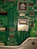
the problematic ports were the last 8 on the left side of the last picture. the middle 8 ports don't have any drives no blue leds.
 
  • Like
Reactions: pricklypunter

pricklypunter

Well-Known Member
Nov 10, 2015
1,704
513
113
Canada
Congrats on the fix, all good now :)

These things can be a real bugger when all you have is a wee 15 or 25W iron to hand, hence my suggestion of pre-heating the board, it takes much less time to ramp the temp up with the iron and doesn't thermal shock the board in the process. When faced with the inevitable kitchen table repair, I usually stick the board in the oven at 150 for a half hour before hitting it with the iron :)
 

BLinux

cat lover server enthusiast
Jul 7, 2016
2,668
1,080
113
artofserver.com
Congrats on the fix, all good now :)

These things can be a real bugger when all you have is a wee 15 or 25W iron to hand, hence my suggestion of pre-heating the board, it takes much less time to ramp the temp up with the iron and doesn't thermal shock the board in the process. When faced with the inevitable kitchen table repair, I usually stick the board in the oven at 150 for a half hour before hitting it with the iron :)
thanks again for all your advice!

it probably doesn't matter, but the iron i was using says it's 45W (generic Craftsman branded one from Sears) and usually works pretty quickly. i think the wick i was using was just transferring all the heat away or something; felt it in my hand. although, the last time i used it, i didn't have the problems I had today. maybe more practice? Or, maybe I need to get those solder pump things?
 

pricklypunter

Well-Known Member
Nov 10, 2015
1,704
513
113
Canada
Probably all of the above, practise makes perfect as they say :p:D

Multi-layered or stacked laminate boards present challenges not seen in single or double-sided boards. In the internal layers you will often have large copper ground and power planes and several very congested signal layers. Sometimes more than one set of these in the same stack. This presents a huge thermal mass to have to overcome before you can even get to the melting point of the solder, worse if the pads you need to rework are actually connected to a large copper plane or heavy track. Add to that the fact that lead free solders have higher wetting and melting points and your wee iron is going to struggle and that's before you add braid to the mix. Preheating the board helps dramatically as it lessens the thermal requirement of the iron to heat that mass, before heating the actual joint. If your iron had a really heavy tip (large thermal mass) on it and took like an hour to get up to temperature, it would have had little trouble, if you see my point.

DeSolder pumps come in a variety of sizes and qualities. But the ones I use, when I have a need, are both anti-static and use replaceable high temp silicone nose cones. They wear a lot faster than the white nylon ones you'll see on cheap pumps, but they wont damage anything by banging into them, as a result of any recoil from the pump acting either. They are also easier to unclog when that happens :)

Really, it comes down to having both the right tools for the job at hand, and the experience in using them to their best ability. Before you know it, you'll be replacing DIMM sockets :D