
F12 did work so thank you for that. I still don't seem to be able to flash the "bios2" but that's not too much of a worry. Good to known that about the bin file though, I'll keep that in mind for next time.F12 should work with ES
Dropbox
www.dropbox.com
Gigabyte MS74-HB0, F07 bios
- Thread starter rig
- Start date
Notice: Page may contain affiliate links for which we may earn a small commission through services like Amazon Affiliates or Skimlinks.


I understand the issue yes, there are way more jumpers actually located there than the manual suggests.That jumper is not identifiable from the manual or from the board, and best guesses seemed to have no impact on the success of flashing either of the bios slots
Judging from pictures and docs the pin count goes 1-2-3 from edge of the board inwards, if you need to set one.
It's great the F12 bios did the job and you don't have to fiddle endlessly.
Appreciate the info, didn't know it was so straightforward.you can make RBU from bin, just a 16bytes footer with checksum.
To finish up, this might be of use to know.
In case you ever need a direct way to dump/program the bios flash. (bios2 included)
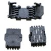
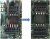
Your boards BIOS and BMC flash chips (SPI flash to be exact) are not soldered directly to the board, but slotted in serviceable (tool less) sockets.
I'm 95% sure your board uses SOP16 form factor SPI flash chips and sockets, I attached 2 screenshots how it functions. (Don't mind the 8 pins, I couldn't find a good 16 pin example but both function all the same)
You can get a cheap ch341a (15-ish dollar) SPI programmer with included adapters to read and write data directly from the chip (Do pay attention you get pcb version 1.7 or newer using 3.3v, as early models used 5v and can kill chips. This guide explains it all)
Attachments
-
 98.5 KB Views: 1
-
 90.8 KB Views: 2
Last edited:
Btw if you'd like, I can help check your BMC dump it actually contains the F07 bios.Yip totally on, been using the Gigabyte ipmitool: gbtipmitool-linux to do the flashing
And it's not overwritten or just empty as it's not uncommon to happen sometimes.
In case you want to be sure and didn't come around to it.
like ASRock Rack usualy does. but don't trust the marking in the socket, better check the pin1 mark printed on the motherboard.Your boards BIOS and BMC flash chips (SPI flash to be exact) are not soldered directly to the board, but slotted in serviceable (tool less) sockets.
not realy correct. the 5V ch341a supplies the BIOS chip with 3.3V, only the data lines are driven by the ch341a directly.Do pay attention you get pcb version 1.7 or newer using 3.3v, as early models used 5v and can kill chips
the signal outputs of the ch341a limit current to < 1mA. nothing is killed.
But the 3.3V version has on anvantage, the supply of the ch341a is stabilized by the 3.3V reg. and a voltage drop of the USBs 5V don't get throught to it. makes flashing more stable. i use the ch341a only in curcuit flashing, my T48 has overcurrent protection(max 350mA) and mostly don't work here.
I think it's pretty neat Asrock Rack and some board manufactures use those.like ASRock Rack usualy does. but don't trust the marking in the socket, better check the pin1 mark printed on the motherboard.
A bios chip failure might not be the most common issue, but is a pain to fix when it's soldered to the board especially thick multi layer boards.
Same if you happen to mess up with a external flash tool or test/develop bios mods and alternate between chips.
You're right about 5v on the ch341a, relating to the 5v data lines and how 3.3v offers other advantages.
I should've clarified better, but also think 5v data pulses still add risks with any 3.3v part not specifically hardend/tolerant for 5v data signals.
4.6ish volt (What I usually see in datasheets) about is the upper limit any degradation starts to happen, but exact voltage and impact differs widely per chip for plethora of reasons.
A 5v ch341a won't immediately kill the chip outright but might degrade it's lifespan in some way, usually increasingly in relation to chip age and workload.
So I generally just recommend the 3.3v "fix" version to not risk any of it, and if you are able/required to use the boards power consider isolating the vcc on the flasher.
I linked this page before as a extra indepth guide.
you never see 5V on that data lines WITH a BIOS chip inserted, they drop to 3.5V or under.but also think 5v data pulses still add risks with any 3.3v part not specifically hardend/tolerant for 5v data signals.
the current of the ch341a data lines can't give more than 1mA