
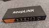
Just arrived. Bought it on Aliexpress flash sale for about $33 shipped, now it's about $40. Seems to work fine. I thought I could dump a few observations someone might find useful here.
Consumes around 1.6W when nothing is connected and around 5.5W when 5 RJ45 clients are connected (one at 2.5G) and SFP cage empty.
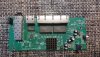
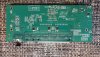
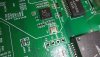
Naturally, I opened it a minute after I confirmed it is working Inside you can find the usual RTL8371B as the main SoC. First four ports are wired directly to the main SoC while the fifth 2.5G port is wired through additional RTL8221B phy. SFP+ cage is wired directly to the SoC. There is a small Winbond EEPROM chip. And the most interesting thing found inside is an unpopulated serial header.
One serial adapter and 3 dupont wires later, this is what it spits out at 9600bps during the boot:
After the boot, it remains silent. However, pressing Enter gives the prompt:
I had no idea what else to do than to give it a question mark. I was hoping to find an interface where I could configure some VLANs at least, but it seems the interface is used for some factory testing only. I did not try anything further.
Consumes around 1.6W when nothing is connected and around 5.5W when 5 RJ45 clients are connected (one at 2.5G) and SFP cage empty.
Naturally, I opened it a minute after I confirmed it is working
Inside you can find the usual RTL8371B as the main SoC. First four ports are wired directly to the main SoC while the fifth 2.5G port is wired through additional RTL8221B phy. SFP+ cage is wired directly to the SoC. There is a small Winbond EEPROM chip. And the most interesting thing found inside is an unpopulated serial header.One serial adapter and 3 dupont wires later, this is what it spits out at 9600bps during the boot:
Code:
▒SERDES_SGMII/fiber1g -14652,LINE 2049

6 12 5078 7 6 9401 7 8 9401 7 a 9401 7 c 9401 1f b 3
error SDS_MODE
LINE 2178
SERDES_HSG 102,LINE 2031
error SDS_MODE
LINE 2178

RTL8371B start SERDES_SGMII/fiber1g 108,LINE 2049

6 12 5078 7 6 9401 7 8 9401 7 a 9401 7 c 9401 1f b 3
error SDS_MODE
LINE 2178
Code:
RTL8371B:
Code:
RTL8371B:?
    rst:        -reset chip
the following is set IOL test mode
        f:    -fix pattern: please input port: 0-7;
        r:    -random pattern: please input port: 0-7;
        10:   -10M MDI: please input port: 0-7;
        11:   -10M MDIx: please input port: 0-7;
        100:    -100M MDI: please input port: 0-7;
        101:    -100M MDIX: please input port: 0-7;
        g1:   -giga mode1: please input port: 0-7;
        g2:   -giga mode2: please input port: 0-7;
        g3:   -giga mode3: please input port: 0-7;
        g4:   -giga mode4: please input port: 0-7;
        1:    -2.5G mode1: please input port: 0-7;
        2:    -2.5G mode2: please input port: 0-7;
        3:    -2.5G mode3: please input port(0~7) and lp;
        4:    -2.5G mode4: please input tone(1~5) and port(0~7);
        5:    -2.5G mode5: please input port: 0-7;
        6:    -2.5G mode6: please input port: 0-7;
the following is set sds test mode,chip sel:8373/8372: 3, 8224: 4;
        sd:    -please input chip: 3 or 4; prbs31:31; sds: 0~1; on/off:1 or 0;
        sd:    -please input chip: 3 or 4; prbs9:9; sds: 0~1; on/off:1 or 0;
        sd:    -please input chip: 3 or 4; tx_8081: 8; sds: 0~1; onoff:1 or 0;
        pre:   -please input chip: 3 or 4; sds: 0~1; pre: 0~63, endis:0~1;
        main:  -please input chip: 3 or 4; sds: 0~1; mamp: 0~63, boost:0~1, endi                                                                             s: 0~1;
        post:  -please input chip: 3 or 4; sds: 0~1; post: 0~63, endis: 0~1;
        tx:    -please input chip: 3 or 4; sds: 0~1; z0:0~15;
        eye:   -please input chip: 3 or 4; sds: 0~1; phyad: 0; frame:0~x;

 dump:   -dump amp cfg;please input chip: 3 or 4; sds:0~1;
Attachments
-
 587.8 KB Views: 44
-
 790.5 KB Views: 51
-
 1,006.8 KB Views: 54
-
 811.6 KB Views: 49
-
 259.4 KB Views: 40