Anyone done a Brocade 6610 fan mod?
- Thread starter Dreece
- Start date
Notice: Page may contain affiliate links for which we may earn a small commission through services like Amazon Affiliates or Skimlinks.
Look at this picture, I am thinking it might be easier to take the case off and buy one of this on top of the switch to blow air toward the switch, basically turn the switch to 2U, 1u for swtich, 1u for the fan. It is not cheap, but it might be the easiest way to cooling switch and reduce noise.Success! (Mostly)
View attachment 13948View attachment 13949
I still need to cut holes in the cover, but it works very well. Almost silent.
I didn’t need the 40mm fans at all. With both 140mm fans, everything is getting quite a bit more air than it did before. And stays much cooler. This switch really is noisy simply because it is 1u.
Don’t buy the 40mm fans I linked. The noise is only 22db, but it is very high pitched.
I did break my rules about the power supply covers... I left off the metal cover and enlarged the hole in the middle of the plastic cover thing. I left 1cm around the edges on the top of the plastic cover under the fan. And the hole is smaller than the part covered by the fan. So everything is still protected. Also, since you won’t be hot swapping the power supply, and it is screwed in to the chassis, the grounding stuff on the metal cover really isn’t needed. Just don’t touch stuff in there!
The only other things I did were remove the 40mm fans, route the wires nicely, hook up one 140mm fan to the red/black wires from the fan tray, and one to the red/black wires from the power supply fan connector. Since my linked fans don’t have colored wires, here is a picture of the fan connector with colored wires.

With 4 fan like this, it could easily push 300CFM of air to the switch and still very quiet.
Yes, without the case protection, some objects might fall into the switch. But on a home lab environment, it should be really rare. We may be able to use some tape to seal the fan rack and switch for tight air control.
Last edited:
@bbqdt Can you show me a close look up picture on your signal gen?done -
View attachment 13979View attachment 13978View attachment 13980
Really is almost silent. A low pitched whir is all I hear.
I can feel a significant amount of cool air flowing out all vents around the switch on the front, back, and sides (including the power supply), so I'm not worried about overheating. All temps are below 30C, some around 15C.
Here is a close up pic of the signal gen if that helps anyone -
View attachment 13981
For mounting, I just stuck it down in a big blob of hot glue, making sure the bottom does not actually touch the chassis.
For cutting holes in the cover - With a pencil, trace the circular inside of the fan and mark the screw holes. Then cut holes with a Dremel or something and drill screw holes. The fans come with screws. I suggest sanding the rough edges down to remove any pieces of metal that might fall off. Also, make absolutely sure that there are no metal flakes on the cover when you are done. I suggest wiping it down all over several times with a paper towel.
Finally - I found that you don't actually need to hook anything up to the red (12v) or black (ground) wires in the fan tray to get the switch to boot. I changed the wiring around so that the signal gen and both fans are running off the power supply fan connector. It was cleaner after all my messing around with the fan tray. The only wires hooked up in the fan tray now are the blue wires to the signal gen, and the LED wires.
How do you connect the cable?
Can I use one signal gen to fake the Tach reading for 3 fan headers?
you quoted a pic ;-), and yes@bbqdt Can you show me a close look up picture on your signal gen?
How do you connect the cable?
Can I use one signal gen to fake the Tach reading for 3 fan headers?
While I haven't tested it, this is likely an easier to setup signal gen for most people.
And the 1u fan thing posted above is likely easier (but much more expensive) than cutting holes and mounting fans. It might not be as quiet and you might need to flip the fans over so they point down. All you would need to do to the switch is disconnect/remove stock fans, hook up signal gen as described to the tac (blue) wire for all 3 fans, take the cover off the switch and power supply, and cut a hole in the plastic power supply cover as described in my previous post (you must be extremely careful to not touch the insides while powered on).
And the 1u fan thing posted above is likely easier (but much more expensive) than cutting holes and mounting fans. It might not be as quiet and you might need to flip the fans over so they point down. All you would need to do to the switch is disconnect/remove stock fans, hook up signal gen as described to the tac (blue) wire for all 3 fans, take the cover off the switch and power supply, and cut a hole in the plastic power supply cover as described in my previous post (you must be extremely careful to not touch the insides while powered on).
Last edited:
I tested this idea on my Aruba S2500-48P. It is idle at about 50W and become pretty hot. Uncomfortable to touch.While I haven't tested it, this is likely an easier to setup signal gen for most people.
And the 1u fan thing posted above is likely easier (but much more expensive) than cutting holes and mounting fans. It might not be as quiet and you might need to flip the fans over so they point down. All you would need to do to the switch is disconnect/remove stock fans, hook up signal gen as described to the tac (blue) wire for all 3 fans, take the cover off the switch and power supply, and cut a hole in the plastic power supply cover as described in my previous post (you must be extremely careful to not touch the insides while powered on).
I took the top off, change 4 40MM fan to 4 120mm Fan. used some zip tie to secure the fan and wire grid. The result is pretty good. Much cooler and much quieter.
I think this can be used to cool off similar 1U devices.

Some zip tie to tie everything down

Put 1U Rack shelf upside on top of the switch. It fit perfect. I could buy some of the 1U Rack spacer to make it prettier

The shelf is not deep enough to cover the whole switch. But it is good enough

On Rack
The tempretures
Before

After

About 27 degree cooler and much quieter!
I'm going to resurrect this one. For anyone else attempting to fan mod brocade 6610:
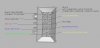
Fan tray has 3 black wires in the connector, but those are not all ground despite the same color. One of them must always be wired to the ground for switch to detect that fan tray is connected (pin 5), the absence or presence of other one (pin 10) determines whether the fan tray is back-to-front airflow or front-to-back. Airflow direction must match with the airflow direction of your PSU, otherwise switch won't boot. Fan tray pinout attached.
LED will come up for the fan tray once the switch is done booting up fully.
Signal generator should be set at 500Hz and 50% duty cycle. You do not need to connect ground on the PWM side of your signal generator, if it has one (mine does).
If you do not connect signal generator to PSU fan header (blue wire), switch will complain about fan tray not being present or having failed.
Personally I skipped PWM control from the switch (yellow wire at pin 9), and will let the fans go full blast or wire up my own fan controller.
Connectors used in fan tray are molex part no 441331000 for the plug, 444281001 for the header, 430300001 for crimp terminals. I decided to buy the latter and use fan tray plug as it already is. These crimp terminals will nicely fit two AWG 27/7 wires (ex from high quality ethernet cable) so with some planning most splices can be avoided. Removing pins is the same as for ATX plugs, except they're smaller. Male pins of these (as linked by bbqdt) are usually made from a tiny sheet of metal folded over to make a pin - this can be unfolded back to flat strong piece, cut to size and used as pin removal tool. I have also cut up some spare noctua fan extenders so I can have normal fan headers instead of hardwiring the fans.
I've connected some fans I had lying around - 2x 80mm noctua fans, one per PSU; and two 140mm noctua fans - one above cpu and asic (silver and nearby black heatsinks towards the ethernet ports), and one for black heatsinks behind 10G SFP+ ports. All temperatures max out at 32 Celsius idle (some as low as 22), with no top cover and no 40mm fans. Still have to cut holes in top cover.
Overall it's a fun mod, and definitely worth doing. Noise levels are waaay down.
Attachments
-
 118.3 KB Views: 255
Very good overview!I'm going to resurrect this one. For anyone else attempting to fan mod brocade 6610:
Fan tray has 3 black wires in the connector, but those are not all ground despite the same color. One of them must always be wired to the ground for switch to detect that fan tray is connected (pin 5), the absence or presence of other one (pin 10) determines whether the fan tray is back-to-front airflow or front-to-back. Airflow direction must match with the airflow direction of your PSU, otherwise switch won't boot. Fan tray pinout attached.
LED will come up for the fan tray once the switch is done booting up fully.
Signal generator should be set at 500Hz and 50% duty cycle. You do not need to connect ground on the PWM side of your signal generator, if it has one (mine does).
If you do not connect signal generator to PSU fan header (blue wire), switch will complain about fan tray not being present or having failed.
Personally I skipped PWM control from the switch (yellow wire at pin 9), and will let the fans go full blast or wire up my own fan controller.
Connectors used in fan tray are molex part no 441331000 for the plug, 444281001 for the header, 430300001 for crimp terminals. I decided to buy the latter and use fan tray plug as it already is. These crimp terminals will nicely fit two AWG 27/7 wires (ex from high quality ethernet cable) so with some planning most splices can be avoided. Removing pins is the same as for ATX plugs, except they're smaller. Male pins of these (as linked by bbqdt) are usually made from a tiny sheet of metal folded over to make a pin - this can be unfolded back to flat strong piece, cut to size and used as pin removal tool. I have also cut up some spare noctua fan extenders so I can have normal fan headers instead of hardwiring the fans.
I've connected some fans I had lying around - 2x 80mm noctua fans, one per PSU; and two 140mm noctua fans - one above cpu and asic (silver and nearby black heatsinks towards the ethernet ports), and one for black heatsinks behind 10G SFP+ ports. All temperatures max out at 32 Celsius idle (some as low as 22), with no top cover and no 40mm fans. Still have to cut holes in top cover.
Overall it's a fun mod, and definitely worth doing. Noise levels are waaay down.
What signal generator was used for this? The one linked above?
Do you have any pictures of the switch after the modifications?
It wasn't the same one, I ordered a cheap one from in-country electronics shop (I live in EU, PL). It doesn't really matter what kind of signal signal generator you use - as far as I know all the cheap ones start distorting at way higher frequencies than 500Hz, so there's nothing to worry about there. The important bit is that it has to accept 12V and output the same voltage as it gets, be a PWM generator, and have adjustable frequency and 50% duty cycle. There's an attached photo of how mine looks like + photo from the shop. What's convenient is that it has one output, but two soldering through-hole pads for it - and I use both.
Photo album here, since some images are apparently too big for the forum to process: Keep in mind that the mod currently looks pretty much like a roadkill - none of the covers have holes made for the fans yet, tray cases aren't in, all the wires are loose and so on, PSUs are uncovered (don't do this unless you are damn sure of what you're doing) - but everything is fully functional at least! =) There's also a photo of what I've done with the fan tray plugs. I made a daisy chained blue wire from PWM signal gen go through fan tray pin to PSU on one side, and other side uses 2nd PWM signal gen output, goes through 3 fan tray pins into other PSU. All of those are two wires crimped to single crimp terminal. And I clearly need a better soldering iron, as this one was barely able to generate enough heat and I'm sure I have some cold joints in there ;D If anyone wants photos of some particular spots, let me know and I'll make some.
Photo album here, since some images are apparently too big for the forum to process: Keep in mind that the mod currently looks pretty much like a roadkill - none of the covers have holes made for the fans yet, tray cases aren't in, all the wires are loose and so on, PSUs are uncovered (don't do this unless you are damn sure of what you're doing) - but everything is fully functional at least! =) There's also a photo of what I've done with the fan tray plugs. I made a daisy chained blue wire from PWM signal gen go through fan tray pin to PSU on one side, and other side uses 2nd PWM signal gen output, goes through 3 fan tray pins into other PSU. All of those are two wires crimped to single crimp terminal. And I clearly need a better soldering iron, as this one was barely able to generate enough heat and I'm sure I have some cold joints in there ;D If anyone wants photos of some particular spots, let me know and I'll make some.
Last edited:
I originally posted this in the ICX6610 thread (link to actual post) but now figure it should go here too as its very relevant.
So, I have successfully halved my temps on my ICX6610-48P.
About 10 or 11 pages back I identified the noise is too much and went on my way...
Had to wait for 2 Noctua 200mm black fans and a pulse generator to show up from Amazon US, everything else I had sitting around already.
Had some 3mm acrylic/perspex or whatever this is that came from an old telecom rack front door, the whole thing was destined to be recycled. A part of this door will be used to replace the lid of the ICX6610.
I didn't want to hack the case lid for my fan mods because... it is not necessary in any way, its pretty much fully reversible modification.
I cut out the shape according to the switch lid flipped and traced it out on the sheet, when it was cut I marked and drilled the holes precisely while the lid was on so the holes are exactly where they need to be. The holes were also countersunk for the original lid screws to be used, perfect.


Meantime my pulse generator arrived and I did 2 things.
1) Create an excel spreadsheet to record the Noctua 100mm fan RPM Hz, while testing the PWM output from a spare mobo/cpu setup.
I used my cheap digital multimeter that can measure temperature and frequency for this, you just need the positive probe on my model.
Based with this information and a similar fan model as the switch ones I added a formula into my spreadsheet to calculate RPM from Hz or Hz from RPM for playing with.
Here is the google sheet you can use to calculate whatever you need for fans
My pulse generator calculator and 200mm Noctua info Google Sheet
2) Used my multimeter to test out the pulse generator with my new found calculations from the excel spreadsheet information. I tested 750Hz and got 22500 RPM exactly on the motherboard, just as per my calculator")


I tested a few different Hz on the mobo once I adjusted the pulse generator accordingly for same output, I used 666Hz for 20000 RPM but anything in this region appears to work fine for the switch, works perfectly, use the multimeter on the pulse generator to set the required Hz (ie RPM required for switch) - At this point I didn't actually measure the switch fans yet, but no matter... just before gutting the fans from the switch I actually measured the frequency and got 650Hz on all 3 fans, so 666 remained..
Next, with the pulse generator worked out, was to do the physical work for mounting the fans as well as wiring, piece of cake.
For the fans, I laid out the fans where I wanted them, covering PSU and the CPU's, they are ginormous so coverage was not difficult, nor placement, and used a scriber thing (anything thats sharp will work) to mark the holes to cut out.

I used a dremel 561 bit which is excellent for cutting this plastic sheet, made it very easy and controllable, even with my crappy cheap non dremel rip off.
The fan mounting holes were also scribed and drilled out to accept regular fan screws of 5mm, also countersunk from the bottom so they dont stick out from under the plastic sheet.

I had some anti noise strip things from years ago I used anywhere where fans contact the sheet and sheet contacts the case, its visible in one of the photos, its stuck not on the switch but on the sheet itself, use masking tape or something that draws on the plastic so you can see it from other side when putting the tape on.
Anyways fans mounted and that part was done, just before I attached the lid on with screws, I put some hot glue over all the fan screws so they are insulated from any possible contact with any switch electronics.

For the PSU to be cooled effectively, I removed the metal top lid and traced out the fan hole, I cut out this portion and kept it, its easily stuck back together when/if returning to stock, you will need it if you are putting on the metal lid on as things are going to short out likely without it..

Wiring was actually piece of cake but YMMW, but im no stranger to wiring and I have experience from more complex wiring jobs through my hobbies...
Anyways I found this instead of me describing it too much, from another thread on this forum, even tho i measured my own to confirm as I recommend anyways...

No stock switch wiring was harmed, I simply removed every part of it from the fan tray and the PSU, the whole rubbish thing is removed in one piece so if it ever gets passed on as stock, its just a simple return operation.
I had also found a very old and broken fan controller that used to be on a pci bracket, I managed to cut the PCB to just fit in the fan tray sideway to have adjustability from outside easily. The broken part was repaired, the regulator snapped off 2 or the 3 soldering pads, so emergency repairs to anchor it down and some wire to repair the electrical connection to the tracks seems to have done the job. Works great now.
Use the diagram above, but for a front to back flow switch you need the 3 grounds, pulse generator and fan controller connected together (and fans grounds if not using controller).
The 12V power is on the bottom 3rd pin from the left, connect that to the pulse generator and fan controller (and fan power if not using controller).
Next pin, bottom, 4th pin from the left and one above it in top row need to be connected to the tone generator output, as well as the power supply fan RPM input too.
My wiring is basically from old motherboard header pins, think reset and power switches, just remove the plastic bits and add a bit of heat shrink, they hold well, needed smaller wire pin for the psu fan header tho, so thats something to consider..

The single green wire going to the PSU, is for the PSU fan trickery

My fans are PWM but im not feeding them PWM, I used some scrap old 3pin pass through and normal connectors from other projects so I can remove lid easily with one connector easily accessed at the back of the switch, at the fan controller output.

All done, just put the lid on,

I forgot to take a pic of the lid screws in place, but they are and the thing is in the rack for testing over next week how it does, temps are 1/2'd since fan switch over.
I also no longer run the blanking plate on the second fan tray. May make a mesh cover to keep any possible larger creatures out of it before I wire it in to my network next week.

This thing is quiet as a mouse 1 meter away, so shouldnt disturb you if your head is next to it... let alone in a rack somewhere else
Speaking of racks, I hope no one has missed the fact my switch is now 2U, something to consider if you are vertically challenged...
The 200mm fans output a LOT of air, its good stuff, also my power draw at the wall is 112W once the switch is booted with only console cable.
Old fan config is 3x40mm 0.81A, new config is 2x200mm 0.08A and a lot more flow.
Here is the whole album link for teardown plus fan mods all pics I took. Includes videos of noise, tho was hard to capture noise after mods, my daughter was lightly playing in the background so its more background noise really then the switch itself, this was fans around 1/2 to 2/3rds speed on the controller..
No fan errors or anything weird going on, as the pulse generator is doing its thing, quite well too.
Here is a shot of temps after 3 hours of on time in the rack with much other heat/etc, keep in mind this is with now closer to 1/2 speed on the fan controller.
If I turn the fan controller up to 11, its still quiet - at 1m hardly audible, in a rack not a chance.
Cheers and enjoy!
So, I have successfully halved my temps on my ICX6610-48P.
About 10 or 11 pages back I identified the noise is too much and went on my way...
Had to wait for 2 Noctua 200mm black fans and a pulse generator to show up from Amazon US, everything else I had sitting around already.
Had some 3mm acrylic/perspex or whatever this is that came from an old telecom rack front door, the whole thing was destined to be recycled. A part of this door will be used to replace the lid of the ICX6610.
I didn't want to hack the case lid for my fan mods because... it is not necessary in any way, its pretty much fully reversible modification.
I cut out the shape according to the switch lid flipped and traced it out on the sheet, when it was cut I marked and drilled the holes precisely while the lid was on so the holes are exactly where they need to be. The holes were also countersunk for the original lid screws to be used, perfect.
Meantime my pulse generator arrived and I did 2 things.
1) Create an excel spreadsheet to record the Noctua 100mm fan RPM Hz, while testing the PWM output from a spare mobo/cpu setup.
I used my cheap digital multimeter that can measure temperature and frequency for this, you just need the positive probe on my model.
| Hz | Reported mobo RPM | Calc RPM from Hz: (Hz * 60) / 2 | Duty % | 29.1 | 862 | 873 | 100 | 27.7 | 825 | 831 | 90 | 22.0 | 650 | 660 | 70 | 16.3 | 485 | 489 | 50 | 11.5 | 343 | 345 | 35 |
Based with this information and a similar fan model as the switch ones I added a formula into my spreadsheet to calculate RPM from Hz or Hz from RPM for playing with.
Here is the google sheet you can use to calculate whatever you need for fans
My pulse generator calculator and 200mm Noctua info Google Sheet
2) Used my multimeter to test out the pulse generator with my new found calculations from the excel spreadsheet information. I tested 750Hz and got 22500 RPM exactly on the motherboard, just as per my calculator
I tested a few different Hz on the mobo once I adjusted the pulse generator accordingly for same output, I used 666Hz for 20000 RPM but anything in this region appears to work fine for the switch, works perfectly, use the multimeter on the pulse generator to set the required Hz (ie RPM required for switch) - At this point I didn't actually measure the switch fans yet, but no matter... just before gutting the fans from the switch I actually measured the frequency and got 650Hz on all 3 fans, so 666 remained..
Next, with the pulse generator worked out, was to do the physical work for mounting the fans as well as wiring, piece of cake.
For the fans, I laid out the fans where I wanted them, covering PSU and the CPU's, they are ginormous so coverage was not difficult, nor placement, and used a scriber thing (anything thats sharp will work) to mark the holes to cut out.
I used a dremel 561 bit which is excellent for cutting this plastic sheet, made it very easy and controllable, even with my crappy cheap non dremel rip off.
The fan mounting holes were also scribed and drilled out to accept regular fan screws of 5mm, also countersunk from the bottom so they dont stick out from under the plastic sheet.
I had some anti noise strip things from years ago I used anywhere where fans contact the sheet and sheet contacts the case, its visible in one of the photos, its stuck not on the switch but on the sheet itself, use masking tape or something that draws on the plastic so you can see it from other side when putting the tape on.
Anyways fans mounted and that part was done, just before I attached the lid on with screws, I put some hot glue over all the fan screws so they are insulated from any possible contact with any switch electronics.
For the PSU to be cooled effectively, I removed the metal top lid and traced out the fan hole, I cut out this portion and kept it, its easily stuck back together when/if returning to stock, you will need it if you are putting on the metal lid on as things are going to short out likely without it..
Wiring was actually piece of cake but YMMW, but im no stranger to wiring and I have experience from more complex wiring jobs through my hobbies...
Anyways I found this instead of me describing it too much, from another thread on this forum, even tho i measured my own to confirm as I recommend anyways...
No stock switch wiring was harmed, I simply removed every part of it from the fan tray and the PSU, the whole rubbish thing is removed in one piece so if it ever gets passed on as stock, its just a simple return operation.
I had also found a very old and broken fan controller that used to be on a pci bracket, I managed to cut the PCB to just fit in the fan tray sideway to have adjustability from outside easily. The broken part was repaired, the regulator snapped off 2 or the 3 soldering pads, so emergency repairs to anchor it down and some wire to repair the electrical connection to the tracks seems to have done the job. Works great now.
Use the diagram above, but for a front to back flow switch you need the 3 grounds, pulse generator and fan controller connected together (and fans grounds if not using controller).
The 12V power is on the bottom 3rd pin from the left, connect that to the pulse generator and fan controller (and fan power if not using controller).
Next pin, bottom, 4th pin from the left and one above it in top row need to be connected to the tone generator output, as well as the power supply fan RPM input too.
My wiring is basically from old motherboard header pins, think reset and power switches, just remove the plastic bits and add a bit of heat shrink, they hold well, needed smaller wire pin for the psu fan header tho, so thats something to consider..
The single green wire going to the PSU, is for the PSU fan trickery
My fans are PWM but im not feeding them PWM, I used some scrap old 3pin pass through and normal connectors from other projects so I can remove lid easily with one connector easily accessed at the back of the switch, at the fan controller output.
All done, just put the lid on,
I forgot to take a pic of the lid screws in place, but they are and the thing is in the rack for testing over next week how it does, temps are 1/2'd since fan switch over.
I also no longer run the blanking plate on the second fan tray. May make a mesh cover to keep any possible larger creatures out of it before I wire it in to my network next week.
This thing is quiet as a mouse 1 meter away, so shouldnt disturb you if your head is next to it... let alone in a rack somewhere else
Speaking of racks, I hope no one has missed the fact my switch is now 2U, something to consider if you are vertically challenged...
The 200mm fans output a LOT of air, its good stuff, also my power draw at the wall is 112W once the switch is booted with only console cable.
Old fan config is 3x40mm 0.81A, new config is 2x200mm 0.08A and a lot more flow.
Here is the whole album link for teardown plus fan mods all pics I took. Includes videos of noise, tho was hard to capture noise after mods, my daughter was lightly playing in the background so its more background noise really then the switch itself, this was fans around 1/2 to 2/3rds speed on the controller..
No fan errors or anything weird going on, as the pulse generator is doing its thing, quite well too.
Here is a shot of temps after 3 hours of on time in the rack with much other heat/etc, keep in mind this is with now closer to 1/2 speed on the fan controller.
If I turn the fan controller up to 11, its still quiet - at 1m hardly audible, in a rack not a chance.
Code:
SSH@bigbeef>show chassis
The stack unit 1 chassis info:

Power supply 1 not present
Power supply 2 (AC - PoE) present, status ok
        Model Number:   23-0000142-02
        Serial Number:  WME
        Firmware Ver:    A
Power supply 2 Fan Air Flow Direction:  Front to Back

Fan 1 ok, speed (auto): [[1]]<->2
Fan 2 not present

Fan controlled temperature: 41.0 deg-C

Fan speed switching temperature thresholds:
                Speed 1: NM<----->84       deg-C
                Speed 2:       79<-----> 87 deg-C (shutdown)

Fan 1 Air Flow Direction:  Front to Back
MAC 1 Temperature Readings:
        Current temperature : 38.0 deg-C
MAC 2 Temperature Readings:
        Current temperature : 40.5 deg-C
CPU Temperature Readings:
        Current temperature : 39.5 deg-C
sensor A Temperature Readings:
        Current temperature : 27.5 deg-C
sensor B Temperature Readings:
        Current temperature : 29.5 deg-C
sensor C Temperature Readings:
        Current temperature : 29.5 deg-C
stacking card Temperature Readings:
        Current temperature : 41.0 deg-C
        Warning level.......: 84.0 deg-C
        Shutdown level......: 87.0 deg-C
Boot Prom MAC : cc4e.243b.a2bc
Management MAC: cc4e.243b.a2bc
Last edited:
I'm going to just remove the PSU cover(s) instead of cutting.Any way to do this without modifying the PSU?
Yeah that is what I am thinking as well, when I decide to pull the trigger on a 6610.I'm going to just remove the PSU cover(s) instead of cutting.
I've got another question. Is it rackable without the metal top cover? I am afraid that by using plastic, the case might lose quite a lot of its structural integrity to hang comfortably by the ears.
These switches are so heavy (especially with two PSU's and two fan sleds), I wouldn't recommend using only the ears to rack. There are rails out there; I think some Dell rails and/or ears work with the 6610.Yeah that is what I am thinking as well, when I decide to pull the trigger on a 6610.
I've got another question. Is it rackable without the metal top cover? I am afraid that by using plastic, the case might lose quite a lot of its structural integrity to hang comfortably by the ears.
I'm going to take the cover or just entire unit to a metal shop and find out if they're willing to fabricate a new cover with 4x 140mm holes in square pattern. Since I have two 6610's, I considered having a shop cut holes in one of the covers, but really don't want to ruin either lid.
FWIW, just inserted second fan sled and PSU into 48P (left PSU is rev. B, right is rev. A) and noticed the noise is considerably less than the 24F model with single rev. A PSU and one fan sled.
FWIW, just inserted second fan sled and PSU into 48P (left PSU is rev. B, right is rev. A) and noticed the noise is considerably less than the 24F model with single rev. A PSU and one fan sled.
Yeah, that's why I want to stick with fabricated metal cover if possible.I like the idea - But have you considered the Electromagnetic compatibility (more EMI because you broke up the Faraday cage)?
Maybe see if the metal shop can make a couple of PSU covers with a bunch of holes; might help with EMI...
Don't do this. PSU are extremely dangerous and this could easily pose a fire/electrocution risk. It might be possible with enough positive air pressure if you do the big fans on top modification to get enough air to passively move through the PSU without having to cut it.I'm going to just remove the PSU cover(s) instead of cutting.
As always, if you're going to go this far, why not buy a unit that is already quiet/modifiable? The question to ask is this- do you really need 40GBe? Really think about this as the Brocade 7250 does everything the 6610 does but without the high noise/heat issue. It also consumes far less power.
Going to the 7250 will also save you time, money, hassle, and protentional serious risks.
Last edited:
I did consider the 7250, but the price of around $300 (compared to about $150 for 6610) was main reason. When buying used equipment for 24/7 home use, I usually purchase another similar or same model for a spare. I couldn't justify twice the cost for two 7250's.Don't do this. PSU are extremely dangerous and this could easily pose a fire/electrocution risk. It might be possible with enough positive air pressure if you do the big fans on top modification to get enough air to passively move through the PSU without having to cut it.
As always, if you're going to go this far, why not buy a unit that is already quiet/modifiable? The question to ask is this- do you really need 40GBe? Really think about this as the Brocade 7250 does everything the 6610 does but without the high noise/heat issue. It also consumes far less power.
Going to the 7250 will also save you time, money, hassle, and protentional serious risks.
I agree that modifying power supplies isn't a good idea, and the 40G ports didn't make any difference to me, but the extra 8x 10G breakout links and price were deciding factors for this purchase.
I guess I can attempt the fan mod without opening the PSU(s) and see how temps run.