Dell PowerEdge C8220 Build and Questions

Notice: Page may contain affiliate links for which we may earn a small commission through services like Amazon Affiliates or Skimlinks.

drabadue

Active Member
Sep 15, 2016
162
54
28
@thomasz - I will try agian tonight to make the SAS and SATA ports work. When looking in BIOS, there are 6 SATA ports (labeled 0-5).

It may be a coincidence, but the motherboard itself, also has 6 ports (SAS will make 4 and 2 SATA ports). Perhaps I need to remove the hard driver interposer board from the rear slot and then check BIOS with my hard drive plugged into the motherboard SATA ports.

I would think that all 12 ports would show up in BIOS with the hard drive interposer board installed.

I do recall when I first tried to get the board fired up, and was using onboard SATA, that I still had 6 SATA connections in BIOS. But for some reason, they were all empty even with my HDD hooked up.

Maybe I will get lucky and the BIOS update will fix my SATA issues as well. Fingers crossed.
 

thomasz

Member
Oct 2, 2016
46
43
18
43
Although these ports worked on my board, I am bit confused with them too. As I know, C602 chipset natively supports 2 SATA III 6.0 Gb/s and 4 SATA II 3.0 Gb/s ports. That makes 6 ports in total.

On the C8220 board, the two SATA ports are #4 and 5, and the four mini-SAS derived ports are SATA #0-3. Then which ones are 6.0 Gb/s and which ones are 3.0? Don't tell me that the four SAS-derived ports are not equal?


@thomasz - I will try agian tonight to make the SAS and SATA ports work. When looking in BIOS, there are 6 SATA ports (labeled 0-5).

It may be a coincidence, but the motherboard itself, also has 6 ports (SAS will make 4 and 2 SATA ports). Perhaps I need to remove the hard driver interposer board from the rear slot and then check BIOS with my hard drive plugged into the motherboard SATA ports.

I would think that all 12 ports would show up in BIOS with the hard drive interposer board installed.

I do recall when I first tried to get the board fired up, and was using onboard SATA, that I still had 6 SATA connections in BIOS. But for some reason, they were all empty even with my HDD hooked up.

Maybe I will get lucky and the BIOS update will fix my SATA issues as well. Fingers crossed.
 

drabadue

Active Member
Sep 15, 2016
162
54
28
@thomasz - I looked up the Intel C602 chipset. Below is the link to Intel Ark page:

Intel® C602 Chipset Product Specifications

Under I/O specification, it lists the total number of SATA ports as 10, and the max number of 6Gb/s SATA ports as 2.

So with that said, if the max number is 10, then maybe that is why only 6 show up in BIOS. We wouldn't be able to have all 12 with the rear HDD interposer board connected since 10 is the max.

I assume this means the interposer board will have to be removed to get the onboard SAS and SATA ports working.

I will know more tonight. I believe I found a setting in BIOS to activate/deactivate the HDD interposer slot, as I remember seeing a setting for it. Perhaps when I reset NVRAM, BIOS knew the interposer board was attached. Maybe if you do not have the interposer board and reset NVRAM, the setting defaults to the onboard ports?
 

drabadue

Active Member
Sep 15, 2016
162
54
28
Good news and bad news.

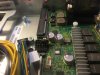
Bad news, I still can not get the onbard SATA and mini SAS connectors working. I tried everything I could think of. I removed the hard drive interposer from the system. Plugged in my hard drive to the SATA port labeled SATA 4. Powered up the computer, entered BIOS, and there were no drives detected in BIOS. Here is a picture:


I tried changing the controller from AHCI to RAID, and changing the link speed from 3.0 to 6.0Gb/s. Nothing worked. I then changed to SATA 5. Same thing. Nothing showed up in BIOS. Made changes to BIOS, and never got a drive to show up. I then tried the mini SAS cable. Still no luck.

I then tried 2 different hard drives hooked up to mini SAS ports 1 and 2, and then tried 2 different hard drives hooked up to SATA 4 and SATA 5. Never got a drive to show up in BIOS.

At this point, I decided to 'go for broke' and clear NVRAM using the jumper, thinking maybe that would reset something and make the SATA ports work. Still no luck.

I do remember @Wictar jumping a front panel connector to get his SATA ports working. I tried this briefly months ago, but it didn't work for me. Since he burnt his board, I decided not to try that method, as I would like to do more research on the pins first (wither with a scope, DMM, or literially tracing them to see where they go).

I think @thomasz may be right. Perhaps I got a faulty board?

Here is a picture of the SATA controller turned off, in hopes that somehow that might make a difference:


Here are the options I got in the 'Boot Manager' menu with the hard drives hooked to SATA or SAS cables:


I even tried turning off the mini SAS ports, hoping that would make a difference:


And here is the screen I would get if I let the computer try to boot. Since it didn't see a HDD, it tried to boot over network and then gave me an error:


So, finally, I went back to what works. The HDD interposer board with my SSD and HDD hooked up and working.


On to the good news... I am confident that the BIOS flash fixed my graphics card woes. When I reset the NVRAM, I was very hesitant to actually do it, since I believe that caused me to lose my graphics card output the very first time I got it working. But, I hooked up the hard drives as seen above, changed the BIOS settings to make sure the correct one was listed as a boot drive, and then booted to windows. When I got to windows, the screen flashed black like normal, and the GTX 780 began outputting video.

Here is a shot of 3 monitors hooked up and working flawlessly. The TV on the left is mainly hooked up so I can have sound output over HDMI from the GTX 780. The monitor in the middle is my 1080p monitor, and it is much easier on the eyes. It is hooked to the GTX 780 with a DVI to HDMI cable. The monitor on the right is hooked to the VGA display port on the motherboard. It is there mainly for boot messages and to be able to see when I can press F2 to enter BIOS:


When it comes to entering BIOS, I have a little trick that I picked up. With my GTX 780, it doesn't actually begin to output display until I windows is loading. So if I unhook the VGA monitor, I can no longer see the BIOS splash screen to know when to press F2. Well, an interesting thing I found out, the USB ports do not turn on during the 'Configuring Memory...Done' screen. They turn on right before the screen flashes and the BIOS splash screen comes up. So if you have a USB drive with a light on it, you can watch for the USB drive to light up to know that the BIOS splash screen is coming. This information is really quite useless if you don't have a VGA monitor hooked up anyway, but I found it interesting.


Although these ports worked on my board, I am bit confused with them too. As I know, C602 chipset natively supports 2 SATA III 6.0 Gb/s and 4 SATA II 3.0 Gb/s ports. That makes 6 ports in total.

On the C8220 board, the two SATA ports are #4 and 5, and the four mini-SAS derived ports are SATA #0-3. Then which ones are 6.0 Gb/s and which ones are 3.0? Don't tell me that the four SAS-derived ports are not equal?
@thomasz I am just guessing, but I think SATA 4 and SATA 5 would be the SATA III 6.0 Gb/s ports. I say this because the are singled out on the mother board, and they are also a direct plug in to the HDD interposer board (for 2.5" HDD's, no cables required). Where as SATA 0-3 are actual ports that require a cable.
 
Last edited:
  • Like
Reactions: Vit K

drabadue

Active Member
Sep 15, 2016
162
54
28
Also, I have no idea why some of my pictures show up as an icon with a red x on them? Is everyone else seeing that too?
 
Last edited:

Vit K

Member
Feb 23, 2017
88
30
18
Hi again,

@drabadue

Great, thank you!

BIOS version 1.0.24, onboard SATA is not working.

I see red exes also, it seems that forum engine does not like dropbox image links. I can copy the link and view image directly.

@thomasz

Thanks )

This cable are you speaking about?

IMG_0042.JPG IMG_0041.JPG IMG_0052.JPG IMG_0053.JPG IMG_0054.JPG

I was able to run system successfully with only cable and a jumper, no mods or wire changes. Of course in this setup power button is not working, but I will try to mod SB as soon as get normal case.

IMG_0036.JPG

When try to mount coolers i discovered that they are not compatible with this system. They fits, but screws are too thin and not hold at all. I have to buy something else.

Sadly, in my system SATA drive was also not detected

IMG_0044.JPG IMG_0037.JPG

I was able to set BMC and connect to it, it is on port 2 NIC when shared config. Credentials was root/root

IMG_0047.JPG

The bios is ancient. I have downloaded new BIOS image and BMC firmware from

Support for PowerEdge C8000 | Dell US

But struggling to get it updated. Direct upload of newest version do nothing, system stuck in update mode and I have to restart it manually. Update to next version return "failed". I will try to run updatefrom os now.

IMG_0050.JPG
 

Attachments

Last edited:

thomasz

Member
Oct 2, 2016
46
43
18
43
@Vit K Thank you! So that is the 1-yellow-1-red-2-black pinout. Based on my previous research I guess that the cable you found is not the motherboard 4-pin power cable, but a cable to power add-on cards. But I could be wrong.
 

thomasz

Member
Oct 2, 2016
46
43
18
43
@drabadue

I also hope SATA4 and 5 are the 6.0 Gb/s ones. Now I am running two SSDs on SATA4 and 5 as RAID0, and four HDDs on the miniSAS as RAID0. No problem so far. It will sound bit weird if members of a RAID are running on different bandwidths.
 

Vit K

Member
Feb 23, 2017
88
30
18
@thomasz

I see. There is a second cable on the manual picture, and this cable lacks it.

K19G9.jpg

And next update, I was able to update BIOS and BMC using MSDOS bootable flash drive. But nothing changed with the SATA with new bios.

IMG_0056.JPG

The SATA disk detected right after I power the addon card with 5v. It is still missed if I connect them to onboard SATA.

IMG_0057.JPG

I used molex to FDD cable, unpinned the FDD part. It fits, but a bit lose. I even shortcircuit cable in process, luckily nothing was fried. The "tiny molex" is hard to unwire, I was unable to do it even with needle.

IMG_0058.JPG

Regarding the onboard SATA again, take a look at the video at 80 second.


Also according to hardware manual:

To facilitate easier and cleaner cable routing, the SAS/SATA signals in the C8220 and C8220X are routed through each sled to the chassis midplane. Configurations that use the onboard controller are cable-less to avoid clutter and additional cost. Hard drive controller connectors are provided near the expansion slots to facilitate easier connection between the controller and system board.

I guess this 6 ports are working if RAID card only. As I get 10 gbit mezzanine working. I will go with ESXI USB boot drive and use ISCSI for the storage.
 
Last edited:

drabadue

Active Member
Sep 15, 2016
162
54
28
@Vit K - you temporary power solution for the HDD interposer board is the same way I first got it working.

I am still confused why some people can get the onboard SATA and mini SAS ports working, and others can not. I still think it has to do with the board version. I believe @Vit K and I both have V1.0 boards.

When try to mount coolers i discovered that they are not compatible with this system. They fits, but screws are too thin and not hold at all. I have to buy something else.
I ran into a similar issue with my first cooler attempt. The LGA2011 uses larger screws for the heat sink than other sockets. But you may still be able to use your heat sinks. I bought the hardware at my local hardware store. I believe they are M4 threads. I do not remember if they were M4 x 0.7 or M4 by 0.5. I think they were by 0.7. You can probably remove the hardware from your coolers and use different hardware.

If you watch the youtube video and pause at the 1:38 mark, you can see light blue sata cables running from front to back. That board is a newer version (either V1.1 or V1.2, not sure which). I do not understand why the sata cables would be ran from one SATA connector to another on the motherboard.

I was able to set BMC and connect to it, it is on port 2 NIC when shared config. Credentials was root/root

@Vit K - forgive my ignorance, but I am curious about the BMC. Did you simply plug an ethernet cable in to NIC port 2, and then run it to another computer? Then use internet to connect to BMC IP address? I am sorry if this is a dumb question, but I am not familiar with BMC or how server networking works. I have never done it.


As I get 10 gbit mezzanine working. I will go with ESXI USB boot drive and use ISCSI for the storage.
@Vit K - Keep me updated on the progress of this as well. I had to google ISCSI to know what it meant. I am very interested to see how this is done. I will do some searching later.
 

drabadue

Active Member
Sep 15, 2016
162
54
28
Also, I believe I figured out how to tell which version of the board you have:

  • V1.0 CN0W6W6G (for sled with Intel Xeon E5-2600 series processor)
  • V1.1 CN0TND55 (for sled with Intel Xeon E5-2600 series processor)
  • V1.2 CN09N44V (for sled with Intel Xeon E5-2600V2 series processor)

This comes from this page:

Dell PowerEdge C8000 PDF Owner's Manual Free Download & Preview


The first 8 digits (CN09N44V) of the ePPID number represents the system board model number and the remaining 14 digits represents the code for the system’s piece part identification code.


And here is a reference to figuring out which version you have via BIOS:

Dell PowerEdge C8000 PDF Owner's Manual Free Download & Preview


With that said, both @Vit K and I have CN0W6W6, which is V1.0.


It appears that @thomasz's first board was CN0WCNW, which is not listed. I find it interesting that the initial board he has, did not have the rear edge slot connectors, similar to @Wictar's board. Wictar said AIDA64 gave him a board model number of:

Motherboard Name is Dell DCS7200S (information from AIDA64).
Which is also listed as the 'Product Name' in the BIOS shot from Thomasz above.

Both mine, and Vit K have a 'Product Name' in BIOS of 'PowerEdge C8220.'

Wictar seemed to get his SATA ports working with a front panel jumper. Thomasz didnt need a jumper for his SATA ports to work on either of his boards, and I am assuming he had a V1.0 board at first, and now has a V1.1 or V1.2. Vit K and I have no luck with our SATA ports. Perhaps it is only an issue with the CN0W6W6 boards?

@thomasz - when you get your board fired up, jump into BIOS and take a picture of the 'Main' BIOS screen.
 

drabadue

Active Member
Sep 15, 2016
162
54
28
Dell heatsinks (it is from some workstation $10/piece new) package materials is heavier that heatsinks themselves. 60mm collers will be installed, I don't think 95w CPUs can be passive cooled.

@Vit K - where did you buy those heatsinks? Do you have a link?
 

Vit K

Member
Feb 23, 2017
88
30
18
@drabadue

Bought them in online shop here in my city, must be leftovers. They out of stock now. If you need cheap tower cooler for 2011, I can recommend ID-COOLING SE-802 2 Direct Touch Heatpipes CPU Cooler with 80mm Fan for Intel & AMD-Newegg.com or DEEPCOOL ICE BLADE 200M CPU Cooler Dual F8mm Heatpipes and Dual 92mm Fans Support Socket LGA 2011 - Newegg.com Newegg is overpriced thought, I see deals 20-30% cheaper here.


I do not understand why the sata cables would be ran from one SATA connector to another on the motherboard.
Same for me, I mean why??

I ran into a similar issue with my first cooler attempt. The LGA2011 uses larger screws for the heat sink than other sockets. But you may still be able to use your heat sinks. I bought the hardware at my local hardware store. I believe they are M4 threads.
Thank you, may be these coolers not useless after all, I will try to find and change the threads.


Did you simply plug an ethernet cable in to NIC port 2, and then run it to another computer? Then use internet to connect to BMC IP address? I am sorry if this is a dumb question, but I am not familiar with BMC or how server networking works. I have never done it.
You need to set up IP address and mode (shared NIC/dedicated NIC) in BIOS, and by default it is set to DHCP so there is a chance you already can connect to it, check router DHCP table for BMC-something name. Right now I do memory test, can't make a screenshot for you, but if you don't find it, I will post pictures later. In case it is dedicated NIC, connect cable to the port with wrench sign. In case you chose shared, it one of the two mail 1Gbit NICs, you can chose it in latest version of BIOS.

Then, just connect cable to the switch and open this address as http. You will see login request, like on home router. root/root worked for me, as it is not DRAC (dell developed remote server control engine) btw, but cheaper OEM aspeed IPMI, still nice. From there you can see temperature/voltage, reboot/shutdown server, set up alerts, and most useful feature is to see screen and mount virtual media to install OS.

Keep me updated on the progress of this as well. I had to google ISCSI to know what it meant. I am very interested to see how this is done. I will do some searching later.
Well I set up ISCSI target on my NAS vm (openmediavault3), to present a volume over 10gbit NIC for C8220. You can even boot from such volume (it is in 10Gb CARD BIOS), if you install OS on it, or you can use any OS ISCSI initiator (Windows has it right from the box, ESXI supports it for storage, Linux and MacOSX probably need some free software) to attach this volume as regular disk (by typing IP and login/password), and you hardly see any difference in speed. The only inconvenience is fiber wire, but if computers are close to each other, it is not a problem.
 

drabadue

Active Member
Sep 15, 2016
162
54
28
You need to set up IP address and mode (shared NIC/dedicated NIC) in BIOS, and by default it is set to DHCP so there is a chance you already can connect to it, check router DHCP table for BMC-something name. Right now I do memory test, can't make a screenshot for you, but if you don't find it, I will post pictures later. In case it is dedicated NIC, connect cable to the port with wrench sign. In case you chose shared, it one of the two mail 1Gbit NICs, you can chose it in latest version of BIOS.

Then, just connect cable to the switch and open this address as http. You will see login request, like on home router. root/root worked for me, as it is not DRAC (dell developed remote server control engine) btw, but cheaper OEM aspeed IPMI, still nice. From there you can see temperature/voltage, reboot/shutdown server, set up alerts, and most useful feature is to see screen and mount virtual media to install OS.

@Vit K - thank you for the explanation. I am not familiar with networks, so I was not sure how this worked. When you said 'switch' I realized what I had done wrong. I was trying to connect directly to the BMC with my laptop. Running an ethernet cable between the two.

Thank you for your help, I got it working! I played with the BIOS settings under 'Server'. Noting the MAC address for the BMC.


I then set the 'Lan Configuration' to 'Dedicated NIC' and the 'BMC IP Source' to '<DHCP>' (some of these settings were default).


From there, I saved BIOS and rebooted the computer.

I had an old Arris SBG6580 modem/router combo laying around that I wasn't using. I plugged the Dell board into one port and my laptop into another and plugged the power for the router into the wall. Then on my laptop, I went to the routers IP address in Google chrome. It was 192.168.0.1.


From there, the router asked me to login. For the SBG6580, the username was 'admin' and the password was 'motorola'.

Under 'Basic' dropdown, I selected 'DHCP'.


Scrolling to the bottom of the page, there is a list of IP and MAC address. I got this router second hand from goodwill, and there was already a lot of MAC and IP's in there. I then searched the 'Client List' for one that matched my BMC's MAC address.


Noting the BMC MAC from the BIOS settings, it ended in '7b'. Looking in the client list table, the last entry is my BMC MAC. So now I have the IP address.


Then it was as simple as entering that IP into my google chrome web browser. When the page first comes up, I got a warning that I had to click the advanced settings and 'continue anyway' button to get around.


As @Vit K mentioned, the username and password are 'root'. After that, I was logged in. I could see the 'sensors' tab, which is what I was most interested in. Both temperature and voltage.


The interesting thing above, is that there is a list of multiple 'Standby' voltages. There is 12v, 5v, and 3.3v standby. I wonder if the signals for these are in the front panel connector?


Also, I learned that I could find the IP address using the command prompt. If you type 'cmd' into the windows search bar, it will open up the command prompt (as most people know). At the command line, type 'arp' and it will give you a list of commands for finding IP and MAC addresses on your network.


Well, I ran 'arp -a' before hooking up the ethernet cable to my laptop.


And then ran it again after.


As you can see, there is a new entry that showed up which just so happens to be the MAC and IP of my BMC.
 
Last edited:
  • Like
Reactions: madLyfe

drabadue

Active Member
Sep 15, 2016
162
54
28
I was very intrigued by the ability to remotely access the server over ethernet. I did some research on the 'Java Remote KVM' option.


When I would click on this option, it would simply give me a file to download. Since this is a Java run application, I downloaded Java. Once downloaded, I tried to open the 'Launch Java KVM Client' with google chrome. Chrome would still try to download a file. So I tried in internet explorer. Logged on to the BMC via it's IP address (192.168.0.10) and navigated to the page shown above. Then when I hit the 'Launch Java KVM client button' a Java splash screen popped up and began thinking. Shortly there after, a Java error popped up:


A quick google search brought me to a write up on the ServeTheHome page about how to add the BMC IP address to the exception list. Here is that link:

How to fix: Java Application Blocked (e.g. when using iKVM)

So, I opened the Java Control Panel, and went to the security tab. From there I could access the 'exception site list'.


A new box will pop up showing you the exception sites. Click add:


Enter in the IP address to the server. Be sure to include the 'http://' or 'https://'. It took me awhile to figure out I needed the 'http://' before the IP address. And it isnt a bad idea to add both addresses to the list:


When you enter in the correct IP, you will probably get this message:


Click continue.

At that point, you are done in the Java settings. You can go back to your internet browser that has the Dell BMC open, and relaunch the Java KVM client. Once again, I had issues with google chrome, but internet explorer worked like a charm.

Here is a screenshot of the server rebooting after I sent the signal remotely:


And here I have entered BIOS remotely. Simply pressed F2 on my laptop:


And here it is in windows.


I will admit, it ran rather slow in windows, but I was just happy to learn and get it working.
 
  • Like
Reactions: madLyfe

MumbleFysh

New Member
Mar 3, 2017
17
8
3
113
Pretty cool this thread is still going, I've been lurking it for quite some time. I have 2 E52600 series CPU's, the board, a 750Watt power supply an the C6100 power cable.

I've gotten some pretty ridiculous setups working in the past so here's to hopefully pulling through on this one too. I'll post a lengthy guide this upcoming week when I have everything together. Great job guys!
 

drabadue

Active Member
Sep 15, 2016
162
54
28
Pretty cool this thread is still going, I've been lurking it for quite some time. I have 2 E52600 series CPU's, the board, a 750Watt power supply an the C6100 power cable.

I've gotten some pretty ridiculous setups working in the past so here's to hopefully pulling through on this one too. I'll post a lengthy guide this upcoming week when I have everything together. Great job guys!

@MumbleFysh - Glad to see another person tackling it! I have been wanting to sit down and write up a guide to everything, but havent had the time to do so yet.

Do you know what version or part number your board is? Do you have the HDD interposer board? Or are you going to try the onboard sata and mini SAS ports?

Keep us posted. I still have not been able to get the on board sata ports working, so if you have the V1.0 board and manage to make them work, let us know how!

Keep us updated. Always nice to see someone else playing with it. Once I get the first one in a case, I am going to try and find a good deal on a V1.2 board next.
 

MumbleFysh

New Member
Mar 3, 2017
17
8
3
113
@drabadue

V1.0, are there any immediate issues I should be aware about?

From what I've read so far, power supply to modded connector to board, jump the two pins and it'll power up? I can research more about the power modes, I know someone had a good writeup going. As for HDD's, I'm gonna try the interposer, onboard, and a raid card. I also have 4-5 different AMD/Nvidia graphic cards I can use to test.

I'm gonna test as much as possible because I want a stable build, I'd likely be using it as my main coding/compiling station.

I think I'm gonna steal @thomaz 's heatsink design that thing looks sick.
 

drabadue

Active Member
Sep 15, 2016
162
54
28
@drabadue

V1.0, are there any immediate issues I should be aware about?

From what I've read so far, power supply to modded connector to board, jump the two pins and it'll power up? I can research more about the power modes, I know someone had a good writeup going. As for HDD's, I'm gonna try the interposer, onboard, and a raid card. I also have 4-5 different AMD/Nvidia graphic cards I can use to test.

I'm gonna test as much as possible because I want a stable build, I'd likely be using it as my main coding/compiling station.

I think I'm gonna steal @thomaz 's heatsink design that thing looks sick.

@Vit K and I both have the v1.0 board. Which is the (0W6W6G) model number. Neither of us (to my knowledge) have been able to get this board to work with the onboard sata and mini SAS connector. I am not sure that it only applies to the V1.0 board, but so far that is my guess.

@thomasz has a V1.1 board and he got all of his ports working by just plugging them in.

If you have the SATA interposer board, you have that backup plan to fall back on. Just be sure to power it. You will need a 5v power and ground. See this post:

Dell PowerEdge C8220 Build and Questions


For the front panel connections, see this post for more info. It is as far as I have gotten with figuring the pins out. It covers the PS_ON line as well as the jumper needed to power up:

Dell PowerEdge C8220 Build and Questions


Graphics card wise, if you have issues, let me know. I had a rough time getting mine going, but a BIOS update seems to have fixed my issue. Since then, I have uninstalled reinstalled, and installed different versions of the drivers, as well as cleared the NVRAM, and it still works like it should.

Post up some pictures when you get it together. It is always nice to see other peoples work.
 

MumbleFysh

New Member
Mar 3, 2017
17
8
3
113
@drabadue

@Vit K and I both have the v1.0 board. Which is the (0W6W6G) model number. Neither of us (to my knowledge) have been able to get this board to work with the onboard sata and mini SAS connector. I am not sure that it only applies to the V1.0 board, but so far that is my guess.
@thomasz has a V1.1 board and he got all of his ports working by just plugging them in.
I have a sneaking suspicion that the SATA ports on the board are actually attached to the interposer, I'll see if it's possible to trace these to prove that; I've dealt with many boards that had a similar setup.

When the interposer board is connected, do the onboard SATA ports work?

For the front panel connections, see this post for more info. It is as far as I have gotten with figuring the pins out. It covers the PS_ON line as well as the jumper needed to power up:

Dell PowerEdge C8220 Build and Questions
Does hibernate/sleep work correctly with the 12V booster, and can the system be woken up from USB?

Graphics card wise, if you have issues, let me know. I had a rough time getting mine going, but a BIOS update seems to have fixed my issue. Since then, I have uninstalled reinstalled, and installed different versions of the drivers, as well as cleared the NVRAM, and it still works like it should.
This isn't anything out of the ordinary, my laptop I'm hacking together now wouldn't do boot from USB or recognize the on board GPU until I flashed the new BIOS. My number one recommendation to everyone here would be to flash to the latest BIOS before any testing.

In previous builds I've wasted hours when things only needed a simple BIOS update.

Post up some pictures when you get it together. It is always nice to see other peoples work.
Will do! Have you done testing of performance between GFX direct on motherboard and GFX using extender cable? I'd be interested to see if there's a performance hit.


______________________
EDIT:

It looks like they changed the interposer board from v1.0 to v1.1, this could have some effect on the onboard sata ports.

 
Last edited: